I have never built solid state coils for a variety of reasons, mostly having to do with money.
Furthermore, with the exception of the commercial coils, most of my coils have been ugly lash-ups, with only the barest nod made to aesthetics.
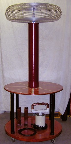
A few years ago, I decided to build one last Tesla coil, this time using all the little tricks I've learned over the years to improve efficiency and performance, and also with the intent to produce a machine of nearly museum quality. Since I have very little experience working with wood, the latter criterion has been difficult to meet, but I've come close, so far.
The overall physical pattern follows one that every Tesla coil builder will be familiar with: a lower deck on wheels which carries the high voltage transformer, spark gap, capacitor, and four supports for the primary deck, the primary deck to which is mounted the eight primary supports and the secondary coil.
Each primary support also has an insulating standoff at the outer edge to hold a grounded brass strike rail. I have already bent the strike rail, and simply need to install it once the primary supports are installed.
The electrical design looks to be fairly efficient on paper. Similarly constructed coils do fairly well, generating streamers 60" - 74" in length from 1,800 watts of input power. The main stumbling block at the moment is the lack of copper for the primary, which will cost some $200 at today's prices. I've managed to miss two dips in the price of copper in the last five years by dint of being broke when the price was low. But now the price is headed back up.
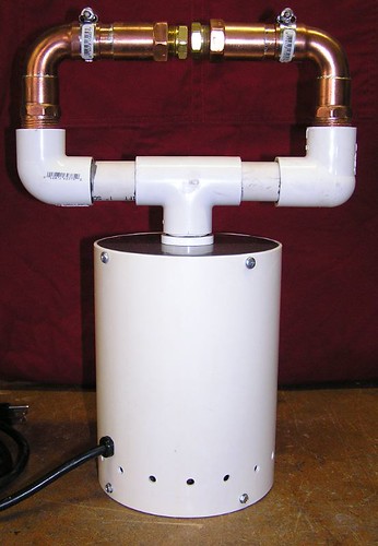
Another goal of this coil is to try out several spark gaps with it, using the best designs others have come up with as well as my own twists, and try out all of them, optimizing performance and tuning each time, to see which one performs best. To that end, I have finished one spark gap already - the "sucker gap":
I've also collected most of the parts for two more gaps - a salient-pole synchronous rotary, and a Richard Quick-style gap.
One thing that I'm doing on this coil which is at least somewhat unusual from most others is the primary connection arrangements. First of all, the primary will be accessed through slots in the primary deck. That allows the primary leads to be shorter since they don't have to go around the edge of the primary deck, reducing wasted inductance. Secondly, the primary connection will be made with a special connector I am designing which will fit neatly between turns, gripping the top and bottom edges of the copper strip with a spring tension clip. This will largely eliminate the projection of the primary connection above the plane of the primary coil, which should eliminate one of the common strike points between secondary and primary.
It occurs to me that the design specifications might interest someone. I've included the basic stats (from memory, there could be mistakes) and I'll post the missing details later, after I have a chance to pull them out of a spreadsheet.
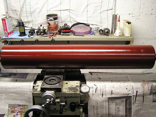
Secondary System
form: 6.25" OD x 38" thin-wall PVC tubing
wire: 1200 turns, 22 AWG double-build motor wire, close-wound
toroid: 30" x 6" fan guard
coating: Glyptal 1201, six coats
Lsec, calculated: 39.5 mH
Lsec, measured: 36 mH
Csec, calculated: 14.4 pF
Ctoroid, calculated: 43.7pF
Fsec, calculated: 105 kHz (loaded)
Fsec, measured:
Primary System
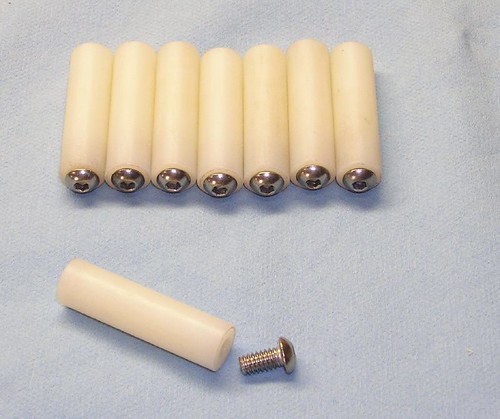
form: eight maple supports w/ strike ring supports
material: 1" x .060" copper strip
turns: 10
diameter innermost turn: 10"
diameter outermost turn: 32"
turn spacing: 0.5"
Lp, calculated: 160 uH
Lp, measured: (I won't be able to provide this number until I build the primary)
HV transformer: 15 kV / 120mA NST w/ anti-resonance+anti-surge "Terry Filter"
Cpri, measured: .02uF
Fpri, calculated: 89kHz (slightly lower than Fsec, for tuning)
Fpri, measured:


No comments:
Post a Comment