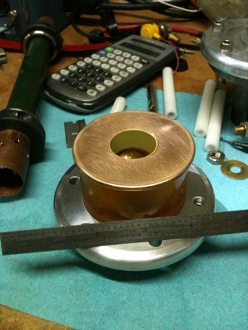
Here's a miserable picture of the thing:

It has a little humidity indicator window which contains an "indicating" silica gel, and through which the output air passes, to give a general indication of whether the supplied air is reasonably dry. The silica gel is impregnated with cobalt chloride (which by the way is both a heavy metal poison AND a carcinogen, so treat with enormous respect) which is all-blue at humidity levels below 5% RH. Unfortunately, that corresponds to a dew point of only about -2ºF. The clay zeolite itself is capable of delivering dew points as low as -20ºF. Since we want our air to be as dry as reasonably practicable, this calls for a down stream air drier of silica gel, which will get us down to -40ºF. Achieving a dew point lower than that would require cryogenic temperatures, or bottled gas. If I used silica gel to do the brute force drying of our lovely unpredictable Colorado air, I would be regenerating it constantly. This two-stage setup with the first stage being self-regenerating strikes me as a pretty good way to get relatively free ultra-dry gas, considering I arrived at the hard part on the cheap. I picked up the air drier at an amateur radio swap meet for, I think, $20 USD.
Now then, the humidity indicator was fine the last time I mucked about with the thing, indicating the supply of dry(ish) air. But when I hauled it out again a few years later (last month) it showed all orange and pink for the first hour after I ran it. Oh dear.
According to the preventive maintenance manual I found floating on the internet, when this happens, the zeolite has become saturated and must be replaced. And oh by the way, attempting to service the drying towers in the field voids the warranty, no user serviceable parts inside, refer servicing to qualified service personnel (ie; factory) and blahblahblah.
Now it's been my (admittedly limited) experience that zeolites can be regenerated (ie, their absorbed molecules desorbed) by heating or application of high vacuum or both. In fact, this is done all the time as a matter of course. There are vacuum pumps that work via the principle. Well and so. Simply running the unit wasn't solving the problem, and the unit was supposed to be self-regenerating.
The PM manual mentioned that the towers would not be properly regenerated if the units "short cycled" (the unit turning on and off too often) or if it was operated at a pressure it outside the range it was designed for. Aha. The last time I'd been using it, I had been trying to get it to run continuously, cycling between the two towers as designed, but delivering dry air at a low pressure and flow. I'd been fiddling about with the pressure regulator (which is used in a strange way in this design) and the compressor cutoff switch. I'd managed to get the operating interval and pressure so far out of whack that the towers weren't getting completely regenerated, resulting in a slow build-up of water vapor.
Once I understood better how the thing needs to operate, I was able to set the regulator and the compressor cutoff switch such that the towers were regenerated (assisted by a heat lamp) in just a few hours.
I still need a downstream silica gel drying cartridge to get the final dew point down in the -30 or -40F range, which I'll either pick up on eBay (I'm not liking the prices I'm finding for new ones) or I'll fabricate, since it looks easy and the bulk agent is cheap.
Dew point monitors/sensors for process gas streams exist, but BOY HOWDY are they expensive. With one, the silica gel cartridge might or might not be necessary. With a (far less expensive) silica gel cartridge, the dew point monitor isn't necessary.
The gas system will probably look something like this:

...except that I can already see that I need a small accumulator and a one-way valve between the air drier and the rest of the system. Its output pressure fluctuates too much as is. It's intended to work into a big reservoir, ie; waveguides.
I'm still figuring this out, because I'm trying to make use of as much on-hand parts as possible. I seem to have nearly everything (certainly the big expensive things, like the vacuum pump) but I'm still short a few odds and ends. I need to be able to control pressure very accurately and repeatably, so a capacitance manometer (Baratron) is probably on the shopping list. I've got thermocouple gauge tubes around, but they aren't useful at higher pressures. The Baratron will cover from above atmosphere to 1x10⁻³ with almost single-Torr precision. (absolute accuracy I care less about than I do precision for this application, assuming the repeatability is there)
The idea is to only pull fresh dry air (or other working gas mix) through the switch when purging it after a shot. We don't want flowing gas during a shot, as it may introduce instabilities we don't want. It would almost certainly affect jitter although I don't happen to care about that yet. Yet.
So that's what the purge valve is for. We open that after a shot. Then close it and pull the switch down to operating pressure. Depending on how hard it turns out to be to maintain the switch at a constant pressure, I might either add some valves to isolate the switch completely, or I might be forced to bleed a small amount of gas through it all the time to maintain the (very low) pressure, in which case I'll plumb the purge valve around a needle valve upstream of the switch.
Speaking of the switch, here's another really excellent phonecam pic of same, attempting to reveal the geometry or relative position of the trigger plane electrode and the adjacent main electrode:
If I had been paying attention when I took this photo, two o-rings in the insulator portion, which are uncompressed, would have been removed, allowing everything to sit as it would when compressed, and the two electrodes would look about .040 closer than they do. But you get the idea.
Now, I haven't yet got a way to model fields, but based on what I've seen in many papers which depict calculated fields through switches, and the few which lead me to think this design with these shapes of electrodes could work -- based on all that I say, I think the adjacent electrode needs to be a hell of a lot more adjacent. Which is to say, I want the round bit to be closer to the plane of the trigger electrode, but still not protruding through the hole.
Right now, when the switch is fully assembled, the main electrodes are separated by .978". The trigger plane opening is 1.017". We want the hole larger than the main electrode spacing, but that's cutting it a bit finely. I think I may -- eventually -- cut new insulator housing pieces from acrylic, with shorter dimensions. I may only have to replace one piece actually. The one which is the short side now looks about right for the new long side, and a new piece cut from acrylic will be the new short side. I only used this horribly yellow bubbly urethane crap because I had it lying around and it was already exactly the the right ID and OD. It would have made better rollers for some mechanical application...
Anyway, shorter spacing is okay only up to a point. I can't let the main electrode separation (the 'D' in the Paschen Pressure-Distance curve) get too low or my operating pressure will be impractically high and pseudochannel operation may not be possible. And since I originally figured all of this out based around one case: the main electrodes I had on hand (specifically, their radius and height) and the right spacing for operating at 10kV in the pseudospark pressure regime... I should probably figure out the limits before I waste time machining new housing bits.
But as it is, I do not believe the field will distort far enough fast enough (through the trigger hole) to ensure not involving the trigger electrode, not to mention achieve the fast current rise time and commutation time I am hoping for. Besides, shorter is lower inductance. There's a reason many commercial switches look the way they do. And there's a reason my switch resembles a scaled down version of the classic T-508 switch originally developed by Physics International and now sold by Titan Pulsed Systems Division of L-3. Yes, this thing is long and huge (tho half the size of a T-508) but if the circuit geometry is right, that will be an advantage, not a disadvantage. If I'd started any smaller I'd have driven myself mad, not to mention would have had to fabricate more parts from scratch.
Having said all that, I think I will give this thing a shot or three as it is before I rebuild the housing. Parts for the gas circuit and some minor tooling to help me get the holes drilled in the end caps. MAYBE, possibly, even using the drill press, which means much sooner rather than waiting until the mill is up again - no promises on that however. It remains to be seen how clever I can be. I'd rather do good work slowly than sloppy work quickly, so if I think I really need the mill to do this without ruining my pretty end caps (which I would be REALLY upset over if I had to make them again) then it'll just have to wait until I get a phase converter. It's mainly an issue of stability and stiffness and whether the rotary table will fit on the drill press table, and how exactly I'm going to mount my end cap fixture tool to the rotary...
This work was supported by the Joss Research Institute.


No comments:
Post a Comment