Since one of the things I need to test the recently completed switch is a very fast, very high voltage trigger source; and since I was already working on a fast coaxial Marx anyway, it just became a high priority again. As a reminder, "fast" in this case means (hopefully) much less than 1uS and hopefully << 10nS; and "high voltage" means not less than 60kV, although I am hoping to stuff enough stages into the housing I have on hand to allow for 80kV or 100kV. If I can find more caps with appropriate specs before I begin final construction, I might even manage 100kV from only eight stages. Stuffing more than eight stages into a housing only 4" x 19" is proving problematical. If I unexpectedly obtain longer housing and insulator tubes before I begin assembly, I'll think about changing my plans.
I accomplished a fair amount of work on the housing this weekend. Because I am not yet set up to weld aluminum, I am still making the bloody housing out of copper and brass which can be silver-soldered to get a flange onto the ground end at the very least. Given that this is a voltage, high impedance, low current device, it doesn't NEED to be made out of those materials, I'm simply working with what is most readily available and has the lowest cost - for me, given the resources at my disposal - to achieve.
I've nearly finished the closure flange for the ground end, through which pass two gas ports (gas & relief), two SHV connectors for charging voltage and trigger, and possibly a small but high quality pressure gauge if I can find room.
I would like to have flanges on both ends, but the amount of effort and cost to make another identical flange for the hot end seems prohibitive for now.
Showing posts with label my triggered switch. Show all posts
Showing posts with label my triggered switch. Show all posts
Monday, June 11, 2012

Saturday, April 14, 2012
distortion-triggered switch is (really) ready to test
Tonight, I finished work on the trigger connector hardware and the copper hardware required to mount the switch to the large test capacitor.
I will be testing with a very small capacitor at first, to try to characterize the switch's behavior, so the big copper hardware won't actually be necessary for a while yet, but it made sense to me to get the difficult work done first.
Have I mentioned that I am not especially fond of machining dead-soft (ETP, which is to say, high conductivity) copper? It tends to bind tools, snapping them, if you aren't careful. I wasn't careful today, so I snapped a small drill bit off in a piece with a lot of time in it. After cooling off, I realized that the hole was nearly through, so I could punch the broken piece of bit through the bottom of the hole. Fortunately, it wasn't a blind hole, or I'd have been well and truly fucked. The bit broke off below the surface. All's well that ends well.
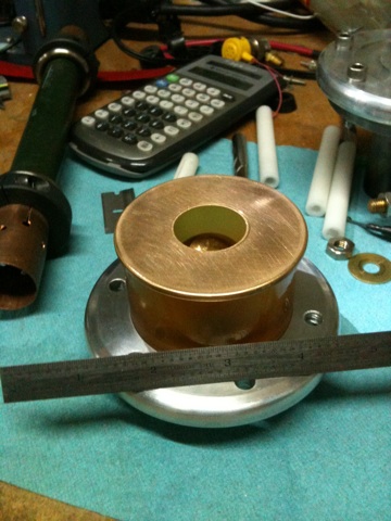
In the fuzzy phonecam image below, you can see that I have added several things...

First, the copper blivets added to the end caps are for connections. The left end blivet has been machined to fit the inside radius of a copper socket which mounts to the capacitor hot stud. After sliding into said socket, the mating surfaces are clamped with three 1/4-20 button-head cap screws (not seen in today's pics because I can't find the damned things, may have to order more) to get adequate (er, it is to be fervently hoped) pressure on the mating surfaces.
The curvature of the two surfaces was made the same. I would have done it differently if I weren't salvaging bits of copper. Copper is expensive. It's REALLY expensive if you don't have bending tools and just decide to arbitrarily machine away everything from a billet that isn't the part you want. I try not to be TOO outrageously wasteful. Have I mentioned that I hate machining copper?
Also visible is the new trigger connector. I am rather proud of that bit of silliness. It is a short piece of the same Delrin™ stock from which the tie-rods were cut, machined on each end to fit the ODs of two tie-rods, thus trapping its ends between them.
I would like to take this moment to say that I love machining Delrin as much or more than I hate machining copper. It's lovely stuff as an engineering resin it's nearly ideal except for acid resistance and a few other edge conditions.
The side facing the axis of the switch has been machined with a curved relief to accommodate the OD of the switch housing, and a slot to accommodate the trigger plane electrode has been milled. That slot incidentally prevents the connection holder from sliding on the tie rods. After the switch is assembled (not unlike a puzzle box, it must be done in a specific sequence) a short length of 8-32 brass rod is threaded into the connection holder, and a corona nut (the brass ball) is added to suppress corona.
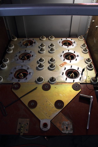
Here is the switch in the process of being test-mounted on one of the six pulse capacitors:

The bolt-terminal of the capacitor is about two inches below that top aluminum plate in the foreground, which is why the copper "socket" is necessary.
That plate was the after-switch "output" plate in the original configuration. For testing this switch it will not be used, and the other capacitors will remain shorted and disconnected from the test setup. For those just joining us, I am using one capacitor out of the six which are in this big pulser system I've got.
The cylindrical housings in the background originally housed ignitrons - one for each capacitor. Now the housings are being used solely to clamp copper connection straps to the top plate - the switching will be done with a single device with all six caps bused together in parallel. This image may clarify matters.
If you're wondering, each cap in the pulser is 60uF, rated for 10,000V charge, 40nH self-inductance, 60kA (or a bit more, I'm still digging) max, and get this - 75% voltage reversal at a discharge frequency of 15kHz. Bused together, capacitor inductances reduce to 6.7nH. Eliminating the ignitrons and the current loop of their housings eliminated another 29 nH of wasted inductance. It'll be a real bang-zoom when all is said and done.
The next part I'll be fabricating (uh, right after I finish designing it) is the test load - a water resistor. Because essentially all of the power of a test shot is dissipated in the load resistor, and since we're talking up to 3,000 joules of stored energy in the big caps, the test resistor must be capable of absorbing all of that energy without getting warm enough to boil the electrolyte. It must also be of reasonable volume and dimensions so as to have low inductance. The resistance is varied by changing the concentration of copper sulfate dissolved in the solution between the contacts. Contact electrodes are brass, and housing may be nearly any plastic. For making connections where some resistance is wanted, long lengths of vinyl hose are frequently used for these resistors. Have a look at this photo of the Marx generators for the Aurora Pulsed Radiation Simulator (sadly, only a memory now) and you'll see some examples.
Once the test load is ready, I will first see what kinds of speed I can get at low current shots (100A or so) using the TM-12 trigger generator and (obviously) a much smaller capacitor. I have several caps to choose from, I haven't decided how fancy (ie, low inductance) I want to get with the small tests. I very much doubt the TM-12 is fast enough to achieve distortion triggering, but the low current limit on the commissioning tests should keep damage to electrodes to a minimum if the thing goes cascade/trigatron on me. Mind you, I also want to run this switch in pseudospark commutation mode. We'll see.
After that, it will be a matter of either building the micro-Marx (an adaption of the "Super Saver Mini Marx" developed by D. Platts at LANL) _OR_ getting one of my other trigger generators working. There's a bloody fast VIG on the premises, but I suspect it has a dead krytron inside. :( I have not yet been able to make it go.
I won't test the switch on the big cap until I've got a really good, fast trigger generator. And all of this is prerequisite and learning for when the time comes to make the big railgap switch commute all 3.6C of charge at once. If it fails to go multi-channel even once, I will have to replace its rails. I would really prefer not to do that, even once. I honestly don't know whether it can be operated in pseudospark mode. I have a lot more research and homework to do.
This work was supported by the Joss Research Institute, Laurel MD.
I will be testing with a very small capacitor at first, to try to characterize the switch's behavior, so the big copper hardware won't actually be necessary for a while yet, but it made sense to me to get the difficult work done first.
Have I mentioned that I am not especially fond of machining dead-soft (ETP, which is to say, high conductivity) copper? It tends to bind tools, snapping them, if you aren't careful. I wasn't careful today, so I snapped a small drill bit off in a piece with a lot of time in it. After cooling off, I realized that the hole was nearly through, so I could punch the broken piece of bit through the bottom of the hole. Fortunately, it wasn't a blind hole, or I'd have been well and truly fucked. The bit broke off below the surface. All's well that ends well.
In the fuzzy phonecam image below, you can see that I have added several things...
First, the copper blivets added to the end caps are for connections. The left end blivet has been machined to fit the inside radius of a copper socket which mounts to the capacitor hot stud. After sliding into said socket, the mating surfaces are clamped with three 1/4-20 button-head cap screws (not seen in today's pics because I can't find the damned things, may have to order more) to get adequate (er, it is to be fervently hoped) pressure on the mating surfaces.
The curvature of the two surfaces was made the same. I would have done it differently if I weren't salvaging bits of copper. Copper is expensive. It's REALLY expensive if you don't have bending tools and just decide to arbitrarily machine away everything from a billet that isn't the part you want. I try not to be TOO outrageously wasteful. Have I mentioned that I hate machining copper?
Also visible is the new trigger connector. I am rather proud of that bit of silliness. It is a short piece of the same Delrin™ stock from which the tie-rods were cut, machined on each end to fit the ODs of two tie-rods, thus trapping its ends between them.
I would like to take this moment to say that I love machining Delrin as much or more than I hate machining copper. It's lovely stuff as an engineering resin it's nearly ideal except for acid resistance and a few other edge conditions.
The side facing the axis of the switch has been machined with a curved relief to accommodate the OD of the switch housing, and a slot to accommodate the trigger plane electrode has been milled. That slot incidentally prevents the connection holder from sliding on the tie rods. After the switch is assembled (not unlike a puzzle box, it must be done in a specific sequence) a short length of 8-32 brass rod is threaded into the connection holder, and a corona nut (the brass ball) is added to suppress corona.
Here is the switch in the process of being test-mounted on one of the six pulse capacitors:
The bolt-terminal of the capacitor is about two inches below that top aluminum plate in the foreground, which is why the copper "socket" is necessary.
That plate was the after-switch "output" plate in the original configuration. For testing this switch it will not be used, and the other capacitors will remain shorted and disconnected from the test setup. For those just joining us, I am using one capacitor out of the six which are in this big pulser system I've got.
The cylindrical housings in the background originally housed ignitrons - one for each capacitor. Now the housings are being used solely to clamp copper connection straps to the top plate - the switching will be done with a single device with all six caps bused together in parallel. This image may clarify matters.
If you're wondering, each cap in the pulser is 60uF, rated for 10,000V charge, 40nH self-inductance, 60kA (or a bit more, I'm still digging) max, and get this - 75% voltage reversal at a discharge frequency of 15kHz. Bused together, capacitor inductances reduce to 6.7nH. Eliminating the ignitrons and the current loop of their housings eliminated another 29 nH of wasted inductance. It'll be a real bang-zoom when all is said and done.
The next part I'll be fabricating (uh, right after I finish designing it) is the test load - a water resistor. Because essentially all of the power of a test shot is dissipated in the load resistor, and since we're talking up to 3,000 joules of stored energy in the big caps, the test resistor must be capable of absorbing all of that energy without getting warm enough to boil the electrolyte. It must also be of reasonable volume and dimensions so as to have low inductance. The resistance is varied by changing the concentration of copper sulfate dissolved in the solution between the contacts. Contact electrodes are brass, and housing may be nearly any plastic. For making connections where some resistance is wanted, long lengths of vinyl hose are frequently used for these resistors. Have a look at this photo of the Marx generators for the Aurora Pulsed Radiation Simulator (sadly, only a memory now) and you'll see some examples.
Once the test load is ready, I will first see what kinds of speed I can get at low current shots (100A or so) using the TM-12 trigger generator and (obviously) a much smaller capacitor. I have several caps to choose from, I haven't decided how fancy (ie, low inductance) I want to get with the small tests. I very much doubt the TM-12 is fast enough to achieve distortion triggering, but the low current limit on the commissioning tests should keep damage to electrodes to a minimum if the thing goes cascade/trigatron on me. Mind you, I also want to run this switch in pseudospark commutation mode. We'll see.
After that, it will be a matter of either building the micro-Marx (an adaption of the "Super Saver Mini Marx" developed by D. Platts at LANL) _OR_ getting one of my other trigger generators working. There's a bloody fast VIG on the premises, but I suspect it has a dead krytron inside. :( I have not yet been able to make it go.
I won't test the switch on the big cap until I've got a really good, fast trigger generator. And all of this is prerequisite and learning for when the time comes to make the big railgap switch commute all 3.6C of charge at once. If it fails to go multi-channel even once, I will have to replace its rails. I would really prefer not to do that, even once. I honestly don't know whether it can be operated in pseudospark mode. I have a lot more research and homework to do.
This work was supported by the Joss Research Institute, Laurel MD.
Monday, April 9, 2012
modifications to distortion triggered switch
After I'd mostly finished my triggered switch, I learned a few things before I got around to testing it, which is very good.
Thing one which I learned is that I am going to need much higher clamping forces to electrically join the brass discharge electrode to the aluminum flanges of the switch. There are formulas - arrived at empirically - for the minimum surface area through which you can pass a given amount of "action" (coulombs, charge, energy, area under the curve) with considerable variances depending on whether it's for pulsed power or a buss bar in a substation.
(if I could have machined them out of a single piece of brass, I would have, okay? Maybe on the next switch.)
That epiphany meant I needed to remove the brass screws from the electrodes and drill and tap them for big fat machine screws coming in from the back.
I also machined off the radius from the rear of the electrodes, since it serves no purpose here (they came with it and I was being lazy) and removing it increases the contact surface area.
And finally, I added a relief around the bolt hole to accommodate an o-ring to ensure a gas tight seal, because this switch will be operated (at least at first) at low pressures - "operating on the left side of the Paschen Curve", as the pulsed power boffins would say.
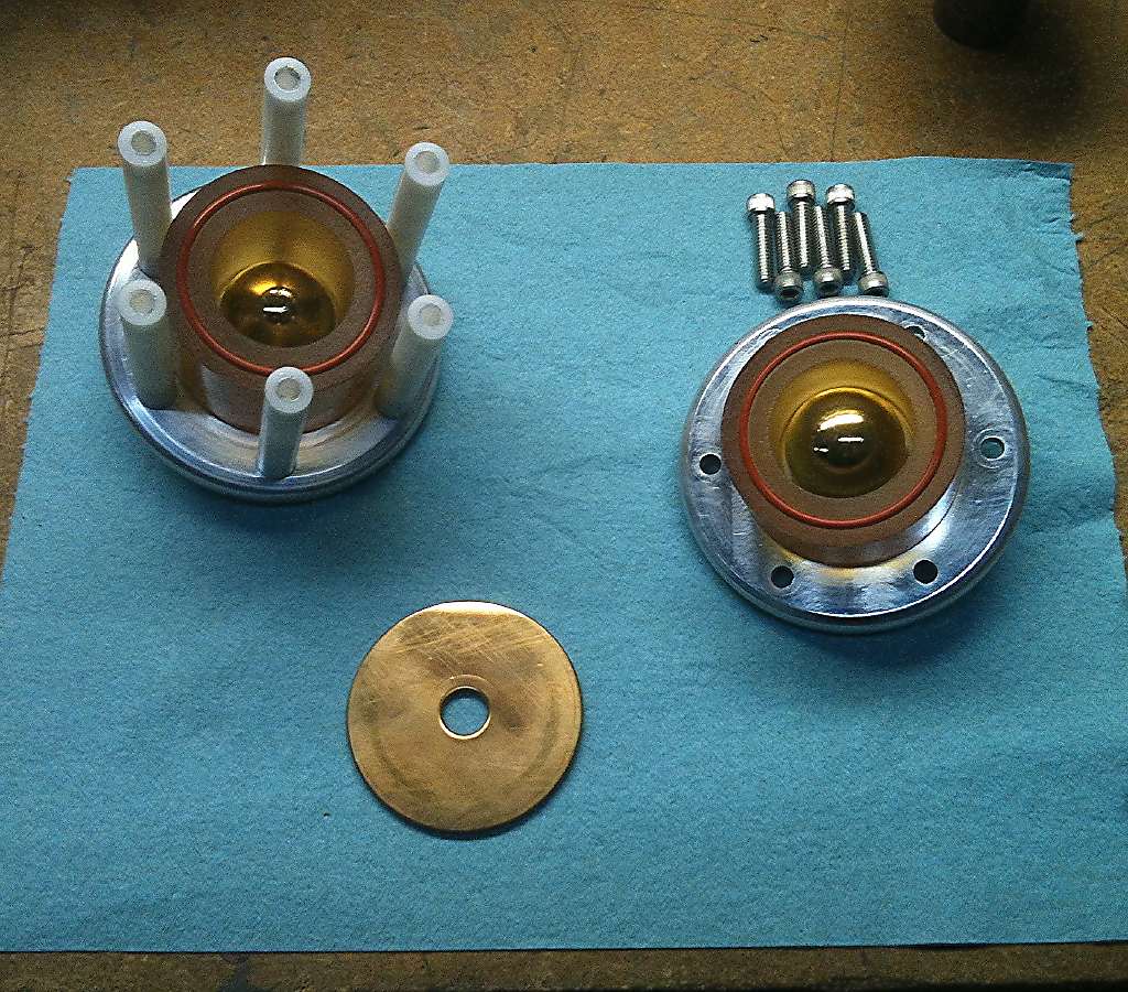
All of these modifications are evident in the photos below:

It should be intuitively obvious to the most casual observer (I just love that snotty phrase) that machining the back of the electrodes changes the gap distance, which implies a change in operating pressure for any given voltage.

How this will sort itself out in forward resistance in the final application remains to be seen. I may either build a new switch, or - more likely - make one new shorter housing piece, keeping the shorter of the old pair, and fabricate six new tie-rods. (I refer to the white Delrin rods which hold the switch together with cap screws - I have called these 'spacers' elsewhere. I shall endeavor to call them tie-rods henceforth, forthwith and like, going forward, man.)
Yeah, one of those end caps could use some cleaning up on the electrode mating surface. That would be the end cap whose center boss did not have to be turned down because I did not mill its o-ring relief too deep. Ahem.
Also, I found after I had machined off the radius of the electrodes, I had to finesse the edge of the gas ports on the inside, as they were covered up by the new base profile of the electrodes.
Really, the only reason this thing isn't fully reassembled and ready to test today, right now (I've got some connection brackets rigged up for it too) is because I don't happen to have the right length bolts handy. I'll be running to the barber and neighborhood hardware store later this morning, after my morning teleconference.
This work was supported by the Joss Research Institute, Laurel MD.
Thing one which I learned is that I am going to need much higher clamping forces to electrically join the brass discharge electrode to the aluminum flanges of the switch. There are formulas - arrived at empirically - for the minimum surface area through which you can pass a given amount of "action" (coulombs, charge, energy, area under the curve) with considerable variances depending on whether it's for pulsed power or a buss bar in a substation.
(if I could have machined them out of a single piece of brass, I would have, okay? Maybe on the next switch.)
That epiphany meant I needed to remove the brass screws from the electrodes and drill and tap them for big fat machine screws coming in from the back.
I also machined off the radius from the rear of the electrodes, since it serves no purpose here (they came with it and I was being lazy) and removing it increases the contact surface area.
And finally, I added a relief around the bolt hole to accommodate an o-ring to ensure a gas tight seal, because this switch will be operated (at least at first) at low pressures - "operating on the left side of the Paschen Curve", as the pulsed power boffins would say.
All of these modifications are evident in the photos below:
It should be intuitively obvious to the most casual observer (I just love that snotty phrase) that machining the back of the electrodes changes the gap distance, which implies a change in operating pressure for any given voltage.
How this will sort itself out in forward resistance in the final application remains to be seen. I may either build a new switch, or - more likely - make one new shorter housing piece, keeping the shorter of the old pair, and fabricate six new tie-rods. (I refer to the white Delrin rods which hold the switch together with cap screws - I have called these 'spacers' elsewhere. I shall endeavor to call them tie-rods henceforth, forthwith and like, going forward, man.)
Yeah, one of those end caps could use some cleaning up on the electrode mating surface. That would be the end cap whose center boss did not have to be turned down because I did not mill its o-ring relief too deep. Ahem.
Also, I found after I had machined off the radius of the electrodes, I had to finesse the edge of the gas ports on the inside, as they were covered up by the new base profile of the electrodes.
Really, the only reason this thing isn't fully reassembled and ready to test today, right now (I've got some connection brackets rigged up for it too) is because I don't happen to have the right length bolts handy. I'll be running to the barber and neighborhood hardware store later this morning, after my morning teleconference.
This work was supported by the Joss Research Institute, Laurel MD.
Monday, March 26, 2012
tooling progress (mill)
A great many projects are waiting for the mill to return to service. I have news about that.
The new phase converter arrived a while back. I've had it mostly-wired up for a week. I've been
er, not well, and also busy as f__k, and so I didn't really think my purchases through. So I still
don't have every thing I need to make it all go. I do have all but one thing, however, and it will
arrive tomorrow afternoon. That one thing is a 3-phase, 4-pole twist-lock connector that I
didin't happen to have on hand. Everything else is in place. When it arrives it will be a matter
of 20 minutes to be online.
Herewith an aside on the futility of saving good quality useful parts for a rainy day:
I have a boat-load of twist-lock connectors of all sorts - recessed inlets and panel mount outlets,
cord connectors, conventional outlets, and more, all for various voltages, currents, phases, et-
bloody-ceteras. And every time I have need such a thing in the past ten years, I have gone through
that collection, and literally nine times out of ten (probably more like 99 in a 100) I have come up
empty handed. The percentages do not make the space taken up (not to mention the capital
value) of them just sitting around here. So I am going to sell every twist-lock and similar power
connector I have (which is a lot, I assure you) on eBay and make a whole bunch of money to re-pay
my recently-raped hobby fund a little, even if I blow them out the door at bargain basement prices
as I intend to do.
I also ran out of money, through some serious miscommunication and well, never mind that.
That's being corrected.
So, by the next time I can find or make some free time in between self-schooling and work, I will
be able to make some parts for the Mad Scientists Light Switch, the triggered spark gap switch,
and so forth and so on.
The new phase converter arrived a while back. I've had it mostly-wired up for a week. I've been
er, not well, and also busy as f__k, and so I didn't really think my purchases through. So I still
don't have every thing I need to make it all go. I do have all but one thing, however, and it will
arrive tomorrow afternoon. That one thing is a 3-phase, 4-pole twist-lock connector that I
didin't happen to have on hand. Everything else is in place. When it arrives it will be a matter
of 20 minutes to be online.
Herewith an aside on the futility of saving good quality useful parts for a rainy day:
I have a boat-load of twist-lock connectors of all sorts - recessed inlets and panel mount outlets,
cord connectors, conventional outlets, and more, all for various voltages, currents, phases, et-
bloody-ceteras. And every time I have need such a thing in the past ten years, I have gone through
that collection, and literally nine times out of ten (probably more like 99 in a 100) I have come up
empty handed. The percentages do not make the space taken up (not to mention the capital
value) of them just sitting around here. So I am going to sell every twist-lock and similar power
connector I have (which is a lot, I assure you) on eBay and make a whole bunch of money to re-pay
my recently-raped hobby fund a little, even if I blow them out the door at bargain basement prices
as I intend to do.
I also ran out of money, through some serious miscommunication and well, never mind that.
That's being corrected.
So, by the next time I can find or make some free time in between self-schooling and work, I will
be able to make some parts for the Mad Scientists Light Switch, the triggered spark gap switch,
and so forth and so on.
Thursday, January 5, 2012
Polarity, trigger, & bias scheme
This will be uncharacteristically concise as my new job + domestic duties = dead-tired Prof. Gomez.
So! It occurred to me I hadn't posted how the switch was to be biased, triggered, etc. here it is, hopefully you can make it out:

Note that power dissipation in the biasing resistors can be non-trivial - we'll need high voltage, high value, reasonably precise resistors for this purpose. Naturally none of those I have lying around are even close to the correct values...
This work was supported by the Joss Research Institute.
So! It occurred to me I hadn't posted how the switch was to be biased, triggered, etc. here it is, hopefully you can make it out:
Note that power dissipation in the biasing resistors can be non-trivial - we'll need high voltage, high value, reasonably precise resistors for this purpose. Naturally none of those I have lying around are even close to the correct values...
This work was supported by the Joss Research Institute.
Monday, January 2, 2012
good news
My air drier -- which is a necessary component for operating the triggered switch -- is in perfect working order, near as I can tell, aside from the pilot lamp in the power switch being burned out.
Here's a miserable picture of the thing:

It has a little humidity indicator window which contains an "indicating" silica gel, and through which the output air passes, to give a general indication of whether the supplied air is reasonably dry. The silica gel is impregnated with cobalt chloride (which by the way is both a heavy metal poison AND a carcinogen, so treat with enormous respect) which is all-blue at humidity levels below 5% RH. Unfortunately, that corresponds to a dew point of only about -2ºF. The clay zeolite itself is capable of delivering dew points as low as -20ºF. Since we want our air to be as dry as reasonably practicable, this calls for a down stream air drier of silica gel, which will get us down to -40ºF. Achieving a dew point lower than that would require cryogenic temperatures, or bottled gas. If I used silica gel to do the brute force drying of our lovely unpredictable Colorado air, I would be regenerating it constantly. This two-stage setup with the first stage being self-regenerating strikes me as a pretty good way to get relatively free ultra-dry gas, considering I arrived at the hard part on the cheap. I picked up the air drier at an amateur radio swap meet for, I think, $20 USD.
Now then, the humidity indicator was fine the last time I mucked about with the thing, indicating the supply of dry(ish) air. But when I hauled it out again a few years later (last month) it showed all orange and pink for the first hour after I ran it. Oh dear.
According to the preventive maintenance manual I found floating on the internet, when this happens, the zeolite has become saturated and must be replaced. And oh by the way, attempting to service the drying towers in the field voids the warranty, no user serviceable parts inside, refer servicing to qualified service personnel (ie; factory) and blahblahblah.
Now it's been my (admittedly limited) experience that zeolites can be regenerated (ie, their absorbed molecules desorbed) by heating or application of high vacuum or both. In fact, this is done all the time as a matter of course. There are vacuum pumps that work via the principle. Well and so. Simply running the unit wasn't solving the problem, and the unit was supposed to be self-regenerating.
The PM manual mentioned that the towers would not be properly regenerated if the units "short cycled" (the unit turning on and off too often) or if it was operated at a pressure it outside the range it was designed for. Aha. The last time I'd been using it, I had been trying to get it to run continuously, cycling between the two towers as designed, but delivering dry air at a low pressure and flow. I'd been fiddling about with the pressure regulator (which is used in a strange way in this design) and the compressor cutoff switch. I'd managed to get the operating interval and pressure so far out of whack that the towers weren't getting completely regenerated, resulting in a slow build-up of water vapor.
Once I understood better how the thing needs to operate, I was able to set the regulator and the compressor cutoff switch such that the towers were regenerated (assisted by a heat lamp) in just a few hours.
I still need a downstream silica gel drying cartridge to get the final dew point down in the -30 or -40F range, which I'll either pick up on eBay (I'm not liking the prices I'm finding for new ones) or I'll fabricate, since it looks easy and the bulk agent is cheap.
Dew point monitors/sensors for process gas streams exist, but BOY HOWDY are they expensive. With one, the silica gel cartridge might or might not be necessary. With a (far less expensive) silica gel cartridge, the dew point monitor isn't necessary.
The gas system will probably look something like this:

...except that I can already see that I need a small accumulator and a one-way valve between the air drier and the rest of the system. Its output pressure fluctuates too much as is. It's intended to work into a big reservoir, ie; waveguides.
I'm still figuring this out, because I'm trying to make use of as much on-hand parts as possible. I seem to have nearly everything (certainly the big expensive things, like the vacuum pump) but I'm still short a few odds and ends. I need to be able to control pressure very accurately and repeatably, so a capacitance manometer (Baratron) is probably on the shopping list. I've got thermocouple gauge tubes around, but they aren't useful at higher pressures. The Baratron will cover from above atmosphere to 1x10⁻³ with almost single-Torr precision. (absolute accuracy I care less about than I do precision for this application, assuming the repeatability is there)
The idea is to only pull fresh dry air (or other working gas mix) through the switch when purging it after a shot. We don't want flowing gas during a shot, as it may introduce instabilities we don't want. It would almost certainly affect jitter although I don't happen to care about that yet. Yet.
So that's what the purge valve is for. We open that after a shot. Then close it and pull the switch down to operating pressure. Depending on how hard it turns out to be to maintain the switch at a constant pressure, I might either add some valves to isolate the switch completely, or I might be forced to bleed a small amount of gas through it all the time to maintain the (very low) pressure, in which case I'll plumb the purge valve around a needle valve upstream of the switch.
Speaking of the switch, here's another really excellent phonecam pic of same, attempting to reveal the geometry or relative position of the trigger plane electrode and the adjacent main electrode:
If I had been paying attention when I took this photo, two o-rings in the insulator portion, which are uncompressed, would have been removed, allowing everything to sit as it would when compressed, and the two electrodes would look about .040 closer than they do. But you get the idea.
Now, I haven't yet got a way to model fields, but based on what I've seen in many papers which depict calculated fields through switches, and the few which lead me to think this design with these shapes of electrodes could work -- based on all that I say, I think the adjacent electrode needs to be a hell of a lot more adjacent. Which is to say, I want the round bit to be closer to the plane of the trigger electrode, but still not protruding through the hole.
Right now, when the switch is fully assembled, the main electrodes are separated by .978". The trigger plane opening is 1.017". We want the hole larger than the main electrode spacing, but that's cutting it a bit finely. I think I may -- eventually -- cut new insulator housing pieces from acrylic, with shorter dimensions. I may only have to replace one piece actually. The one which is the short side now looks about right for the new long side, and a new piece cut from acrylic will be the new short side. I only used this horribly yellow bubbly urethane crap because I had it lying around and it was already exactly the the right ID and OD. It would have made better rollers for some mechanical application...
Anyway, shorter spacing is okay only up to a point. I can't let the main electrode separation (the 'D' in the Paschen Pressure-Distance curve) get too low or my operating pressure will be impractically high and pseudochannel operation may not be possible. And since I originally figured all of this out based around one case: the main electrodes I had on hand (specifically, their radius and height) and the right spacing for operating at 10kV in the pseudospark pressure regime... I should probably figure out the limits before I waste time machining new housing bits.
But as it is, I do not believe the field will distort far enough fast enough (through the trigger hole) to ensure not involving the trigger electrode, not to mention achieve the fast current rise time and commutation time I am hoping for. Besides, shorter is lower inductance. There's a reason many commercial switches look the way they do. And there's a reason my switch resembles a scaled down version of the classic T-508 switch originally developed by Physics International and now sold by Titan Pulsed Systems Division of L-3. Yes, this thing is long and huge (tho half the size of a T-508) but if the circuit geometry is right, that will be an advantage, not a disadvantage. If I'd started any smaller I'd have driven myself mad, not to mention would have had to fabricate more parts from scratch.
Having said all that, I think I will give this thing a shot or three as it is before I rebuild the housing. Parts for the gas circuit and some minor tooling to help me get the holes drilled in the end caps. MAYBE, possibly, even using the drill press, which means much sooner rather than waiting until the mill is up again - no promises on that however. It remains to be seen how clever I can be. I'd rather do good work slowly than sloppy work quickly, so if I think I really need the mill to do this without ruining my pretty end caps (which I would be REALLY upset over if I had to make them again) then it'll just have to wait until I get a phase converter. It's mainly an issue of stability and stiffness and whether the rotary table will fit on the drill press table, and how exactly I'm going to mount my end cap fixture tool to the rotary...
This work was supported by the Joss Research Institute.
Here's a miserable picture of the thing:
It has a little humidity indicator window which contains an "indicating" silica gel, and through which the output air passes, to give a general indication of whether the supplied air is reasonably dry. The silica gel is impregnated with cobalt chloride (which by the way is both a heavy metal poison AND a carcinogen, so treat with enormous respect) which is all-blue at humidity levels below 5% RH. Unfortunately, that corresponds to a dew point of only about -2ºF. The clay zeolite itself is capable of delivering dew points as low as -20ºF. Since we want our air to be as dry as reasonably practicable, this calls for a down stream air drier of silica gel, which will get us down to -40ºF. Achieving a dew point lower than that would require cryogenic temperatures, or bottled gas. If I used silica gel to do the brute force drying of our lovely unpredictable Colorado air, I would be regenerating it constantly. This two-stage setup with the first stage being self-regenerating strikes me as a pretty good way to get relatively free ultra-dry gas, considering I arrived at the hard part on the cheap. I picked up the air drier at an amateur radio swap meet for, I think, $20 USD.
Now then, the humidity indicator was fine the last time I mucked about with the thing, indicating the supply of dry(ish) air. But when I hauled it out again a few years later (last month) it showed all orange and pink for the first hour after I ran it. Oh dear.
According to the preventive maintenance manual I found floating on the internet, when this happens, the zeolite has become saturated and must be replaced. And oh by the way, attempting to service the drying towers in the field voids the warranty, no user serviceable parts inside, refer servicing to qualified service personnel (ie; factory) and blahblahblah.
Now it's been my (admittedly limited) experience that zeolites can be regenerated (ie, their absorbed molecules desorbed) by heating or application of high vacuum or both. In fact, this is done all the time as a matter of course. There are vacuum pumps that work via the principle. Well and so. Simply running the unit wasn't solving the problem, and the unit was supposed to be self-regenerating.
The PM manual mentioned that the towers would not be properly regenerated if the units "short cycled" (the unit turning on and off too often) or if it was operated at a pressure it outside the range it was designed for. Aha. The last time I'd been using it, I had been trying to get it to run continuously, cycling between the two towers as designed, but delivering dry air at a low pressure and flow. I'd been fiddling about with the pressure regulator (which is used in a strange way in this design) and the compressor cutoff switch. I'd managed to get the operating interval and pressure so far out of whack that the towers weren't getting completely regenerated, resulting in a slow build-up of water vapor.
Once I understood better how the thing needs to operate, I was able to set the regulator and the compressor cutoff switch such that the towers were regenerated (assisted by a heat lamp) in just a few hours.
I still need a downstream silica gel drying cartridge to get the final dew point down in the -30 or -40F range, which I'll either pick up on eBay (I'm not liking the prices I'm finding for new ones) or I'll fabricate, since it looks easy and the bulk agent is cheap.
Dew point monitors/sensors for process gas streams exist, but BOY HOWDY are they expensive. With one, the silica gel cartridge might or might not be necessary. With a (far less expensive) silica gel cartridge, the dew point monitor isn't necessary.
The gas system will probably look something like this:
...except that I can already see that I need a small accumulator and a one-way valve between the air drier and the rest of the system. Its output pressure fluctuates too much as is. It's intended to work into a big reservoir, ie; waveguides.
I'm still figuring this out, because I'm trying to make use of as much on-hand parts as possible. I seem to have nearly everything (certainly the big expensive things, like the vacuum pump) but I'm still short a few odds and ends. I need to be able to control pressure very accurately and repeatably, so a capacitance manometer (Baratron) is probably on the shopping list. I've got thermocouple gauge tubes around, but they aren't useful at higher pressures. The Baratron will cover from above atmosphere to 1x10⁻³ with almost single-Torr precision. (absolute accuracy I care less about than I do precision for this application, assuming the repeatability is there)
The idea is to only pull fresh dry air (or other working gas mix) through the switch when purging it after a shot. We don't want flowing gas during a shot, as it may introduce instabilities we don't want. It would almost certainly affect jitter although I don't happen to care about that yet. Yet.
So that's what the purge valve is for. We open that after a shot. Then close it and pull the switch down to operating pressure. Depending on how hard it turns out to be to maintain the switch at a constant pressure, I might either add some valves to isolate the switch completely, or I might be forced to bleed a small amount of gas through it all the time to maintain the (very low) pressure, in which case I'll plumb the purge valve around a needle valve upstream of the switch.
Speaking of the switch, here's another really excellent phonecam pic of same, attempting to reveal the geometry or relative position of the trigger plane electrode and the adjacent main electrode:
If I had been paying attention when I took this photo, two o-rings in the insulator portion, which are uncompressed, would have been removed, allowing everything to sit as it would when compressed, and the two electrodes would look about .040 closer than they do. But you get the idea.
Now, I haven't yet got a way to model fields, but based on what I've seen in many papers which depict calculated fields through switches, and the few which lead me to think this design with these shapes of electrodes could work -- based on all that I say, I think the adjacent electrode needs to be a hell of a lot more adjacent. Which is to say, I want the round bit to be closer to the plane of the trigger electrode, but still not protruding through the hole.
Right now, when the switch is fully assembled, the main electrodes are separated by .978". The trigger plane opening is 1.017". We want the hole larger than the main electrode spacing, but that's cutting it a bit finely. I think I may -- eventually -- cut new insulator housing pieces from acrylic, with shorter dimensions. I may only have to replace one piece actually. The one which is the short side now looks about right for the new long side, and a new piece cut from acrylic will be the new short side. I only used this horribly yellow bubbly urethane crap because I had it lying around and it was already exactly the the right ID and OD. It would have made better rollers for some mechanical application...
Anyway, shorter spacing is okay only up to a point. I can't let the main electrode separation (the 'D' in the Paschen Pressure-Distance curve) get too low or my operating pressure will be impractically high and pseudochannel operation may not be possible. And since I originally figured all of this out based around one case: the main electrodes I had on hand (specifically, their radius and height) and the right spacing for operating at 10kV in the pseudospark pressure regime... I should probably figure out the limits before I waste time machining new housing bits.
But as it is, I do not believe the field will distort far enough fast enough (through the trigger hole) to ensure not involving the trigger electrode, not to mention achieve the fast current rise time and commutation time I am hoping for. Besides, shorter is lower inductance. There's a reason many commercial switches look the way they do. And there's a reason my switch resembles a scaled down version of the classic T-508 switch originally developed by Physics International and now sold by Titan Pulsed Systems Division of L-3. Yes, this thing is long and huge (tho half the size of a T-508) but if the circuit geometry is right, that will be an advantage, not a disadvantage. If I'd started any smaller I'd have driven myself mad, not to mention would have had to fabricate more parts from scratch.
Having said all that, I think I will give this thing a shot or three as it is before I rebuild the housing. Parts for the gas circuit and some minor tooling to help me get the holes drilled in the end caps. MAYBE, possibly, even using the drill press, which means much sooner rather than waiting until the mill is up again - no promises on that however. It remains to be seen how clever I can be. I'd rather do good work slowly than sloppy work quickly, so if I think I really need the mill to do this without ruining my pretty end caps (which I would be REALLY upset over if I had to make them again) then it'll just have to wait until I get a phase converter. It's mainly an issue of stability and stiffness and whether the rotary table will fit on the drill press table, and how exactly I'm going to mount my end cap fixture tool to the rotary...
This work was supported by the Joss Research Institute.
Thursday, December 29, 2011
Step 1 of {mumble} complete!
As you can hopefully see from the no-doubt indistinct phone-cam shot accompanying this post, the reconfiguration of the trigger electrode is complete.

Next step is to add the extra holes to the switch end-caps that I mentioned in my previous post. To do that, I need to be able to mount the lathe mount I made for the switch end caps into the mill vise. And to do that, I need a big pair of vee blocks than the pair I have. Right then, one more item added to the shopping list. Oi. Been meaning to get a pair for a very long time. I scored a small precision pair on eBay some time ago, but they are too small for this job.
After the mods to the switch are complete, I have to focus on getting the gas handling system and some kind of very fast trigger ready.
For the gas handling part, I have an air drier the media of which needs drying out, a vacuum system which lacks a precision manometer, and so on - about 3/4 of what I need is ready to go or can be. My vacuum system is technically down, but I only need the roughing pump, there's an additional port for that.
As for triggering this thing in field distortion mode, I do not believe the EG&G TM-12 which I have on hand, or indeed any trigger source EG&G made -commercially- is fast enough (gasp! Yes, I said it, tho I'll be delighted to be proved wrong, it just wasn't their usual bailiwick) to multichannel this sucker without going trigatron on me. Trigatron operation means a spark develops between the adjacent electrode and the trigger electrode, and that spark provides the ionization which fires the gap. Some switches are designed to work that way. Unfortunately, in this switch it would probably result in very bad erosion of the trigger electrode, so it's an operating mode to be avoided. I also don't believe that the Pacific-Atlantic Vector Inversion Generator (trigger pulser) is in working condition, although I haven't nailed that status down with certainty yet. I have another miniature VIG in a trigger panel for a Pulsatron I scored from eBay, but I don't know yet whether I can get that unit working either. There are one or two other options, and of course there is always the Marx, except that I think its output might be too high. I know, right? There are worse problems to have. OTOH, it isn't built yet.
Odds are good that I'll try running the switch with just the TM-12 for a trigger, at least once, because I'm dying to run the thing at all. Hopefully running it at relatively low power levels will keep electrode erosion down. The first test shots will be done with a 100Ω load at 10kV, resulting in 1MW dissipated in the load resistor.
And one way or another, I have to get the Bridgeport some 3-ph power again because so many parts and features I need to make require a mill. I am looking at a rotary phase converter from American Rotary, most likely. I'm done mucking about with inverter VFDs, I think. And if any reader is wondering why one doesn't simply swap the motor for a single-phase version, there are various very good reasons which I have arrived at through my own homework and which I feel certain the reader will find far more convincing if she arrives at them himself.
I think I shall shop for a capacitance manometer (Baratron, MKS Instruments) and a simple display for same (Duniway's TeraNova displays are nice) on eBay. I'll need to be able to read the gas pressure in the switch accurately and repeatably. It will take time to find what I need for a price I'm willing to pay, so I'd best start searching now.
This work was supported by The Joss Research Institute, Laurel, MD, USA.
Next step is to add the extra holes to the switch end-caps that I mentioned in my previous post. To do that, I need to be able to mount the lathe mount I made for the switch end caps into the mill vise. And to do that, I need a big pair of vee blocks than the pair I have. Right then, one more item added to the shopping list. Oi. Been meaning to get a pair for a very long time. I scored a small precision pair on eBay some time ago, but they are too small for this job.
After the mods to the switch are complete, I have to focus on getting the gas handling system and some kind of very fast trigger ready.
For the gas handling part, I have an air drier the media of which needs drying out, a vacuum system which lacks a precision manometer, and so on - about 3/4 of what I need is ready to go or can be. My vacuum system is technically down, but I only need the roughing pump, there's an additional port for that.
As for triggering this thing in field distortion mode, I do not believe the EG&G TM-12 which I have on hand, or indeed any trigger source EG&G made -commercially- is fast enough (gasp! Yes, I said it, tho I'll be delighted to be proved wrong, it just wasn't their usual bailiwick) to multichannel this sucker without going trigatron on me. Trigatron operation means a spark develops between the adjacent electrode and the trigger electrode, and that spark provides the ionization which fires the gap. Some switches are designed to work that way. Unfortunately, in this switch it would probably result in very bad erosion of the trigger electrode, so it's an operating mode to be avoided. I also don't believe that the Pacific-Atlantic Vector Inversion Generator (trigger pulser) is in working condition, although I haven't nailed that status down with certainty yet. I have another miniature VIG in a trigger panel for a Pulsatron I scored from eBay, but I don't know yet whether I can get that unit working either. There are one or two other options, and of course there is always the Marx, except that I think its output might be too high. I know, right? There are worse problems to have. OTOH, it isn't built yet.
Odds are good that I'll try running the switch with just the TM-12 for a trigger, at least once, because I'm dying to run the thing at all. Hopefully running it at relatively low power levels will keep electrode erosion down. The first test shots will be done with a 100Ω load at 10kV, resulting in 1MW dissipated in the load resistor.
And one way or another, I have to get the Bridgeport some 3-ph power again because so many parts and features I need to make require a mill. I am looking at a rotary phase converter from American Rotary, most likely. I'm done mucking about with inverter VFDs, I think. And if any reader is wondering why one doesn't simply swap the motor for a single-phase version, there are various very good reasons which I have arrived at through my own homework and which I feel certain the reader will find far more convincing if she arrives at them himself.
I think I shall shop for a capacitance manometer (Baratron, MKS Instruments) and a simple display for same (Duniway's TeraNova displays are nice) on eBay. I'll need to be able to read the gas pressure in the switch accurately and repeatably. It will take time to find what I need for a price I'm willing to pay, so I'd best start searching now.
This work was supported by The Joss Research Institute, Laurel, MD, USA.
Tuesday, December 27, 2011
why so serious?
For some time now, and as previously reported, I have been unable to make much headway on any of my Mad Science projects. There are various reasons for this, some good, some not-so-good.
Here are some good ones:
* I've been unemployed since May, and every single project needs parts which must be purchased. Many of said parts are relatively inexpensive, but there has been NO disposable income until recently, and that due solely to the generosity of friends. More on this down below.
* my wife just went through total hip replacement surgery. If you're not familiar with that, please take my word for it that it is brutal and very challenging to recover from. This will be the third such surgery she has endured. Recover takes months, happens at home, and I am all of the nursing staff (poor girl).
* I've got health issues of my own which are severely hampering my ability to do what I'd like to be doing. I'll spare you the details.
And now the good news: I start a new job in January and should have paychecks coming in mid-month.
I've also been honored to receive an honorarium / stipend / fellowship from The Joss Research Institute, a private R&D firm in Maryland. It came with some funds which for now went into paying bills, but which will be pulled back out of my future paychecks and earmarked exclusively for expenditure on my science projects. I think it is entirely appropriate that said money be used exclusively for that, especially given the spirit in which it was given, which was to help remove obstacles to my getting shit done. It's also easy to do this since our credit union gives us several free accounts to stick money into for various purposes.
I have to say, I am quite flattered given the smarts of the guys who gave it to me. We all communicate with several other folks with similar and branching interests along the lines of pulsed power, high voltage, high vacuum, physics experiments, lasers,
To make this post a little better than a place-holder, I offer the following:
My Triggered Spark Gap Switch requires some rework before I strap it to one of the 3kJ pulse caps and a pulse resistor and transfer a 1 kA / 1MW pulse through it.
It turns out I can do at least part of said re-work without spending money. I just need to get a different project off of the lathe so I can work on the trigger plane electrode. Two things need doing:
Thing One
I'll be making the ID about twice as large, all the better to pass a large diffuse plasma discharge, my dear, preferably without actually involving the trigger electrode - remember, this is a field-distortion switch, we hope)
-and-
Thing Two
I'll be removing the radius on the ID, leaving instead an acute angle with a sharp edge. This angle will be tapered on the large-gap side and in-plane on the small-gap side. The better to distort the field with, my dear. However, a sharp-edged trigger plane must be PREZACKLY biased with respect to the ratio of the two gap distances. I have the vague recollection that the ratio of diameter to main electrode distance was to be in the range of 1.0 - 1.6, but my memory is notoriously unreliable, so we'll just leave that a hypothetical until I find the collection of photons and spins states that constitutes a "white paper" these days...
Looky here:
That brass disk with the hole in it, bottom-center, is the trigger plane electrode. The hole in the middle needs to be about twice as big or a bit bigger. Someone mentioned (in some switch white paper I have somewhere) an empirically-arrived-at rule of thumb for main electrode distance vs. hole size for this style of switch, but finding it again will take some time...
As is probably obvious, this switch has not had a single shot through it. I realized after I finished it that the changes were needed. Just now got around to diddling with it in between thirteen other things.
I lied unintentionally: THREE things need doing. A second set of holes in each switch end plate needs to be made, identical to the ones that are there now, but countersunk in the opposite direction, for bolting the switch into a transmission line or to coaxial test loads. Having a bolt circle lets me fashion large-diameter connections and current paths which translate in the general case to low distributed inductance, which informs the minimum attainable pulse rise time. Readers who have read my earlier descriptive material here and on Flickr will have gleaned that a big part of what I am hoping to do with this switch is not merely transfer big lumps of energy around, but to achieve very fast switching speeds and commutation times -- fast, that is, for a rank amateur with not formal schooling in pulsed power!
Oh yes, I will be studying calculus in 2012, or that's the plan anyway.
I'm just not in any shape to finish the project currently occupying the lathe and which I don't want to re-center later. Humph. But I am not idle. I'll get some of the above done soonish I think. Things ought to be a LOT better in 2012 than they have in a very long time.
Stay tuned.
Here are some good ones:
* I've been unemployed since May, and every single project needs parts which must be purchased. Many of said parts are relatively inexpensive, but there has been NO disposable income until recently, and that due solely to the generosity of friends. More on this down below.
* my wife just went through total hip replacement surgery. If you're not familiar with that, please take my word for it that it is brutal and very challenging to recover from. This will be the third such surgery she has endured. Recover takes months, happens at home, and I am all of the nursing staff (poor girl).
* I've got health issues of my own which are severely hampering my ability to do what I'd like to be doing. I'll spare you the details.
And now the good news: I start a new job in January and should have paychecks coming in mid-month.
I've also been honored to receive an honorarium / stipend / fellowship from The Joss Research Institute, a private R&D firm in Maryland. It came with some funds which for now went into paying bills, but which will be pulled back out of my future paychecks and earmarked exclusively for expenditure on my science projects. I think it is entirely appropriate that said money be used exclusively for that, especially given the spirit in which it was given, which was to help remove obstacles to my getting shit done. It's also easy to do this since our credit union gives us several free accounts to stick money into for various purposes.
I have to say, I am quite flattered given the smarts of the guys who gave it to me. We all communicate with several other folks with similar and branching interests along the lines of pulsed power, high voltage, high vacuum, physics experiments, lasers,
To make this post a little better than a place-holder, I offer the following:
My Triggered Spark Gap Switch requires some rework before I strap it to one of the 3kJ pulse caps and a pulse resistor and transfer a 1 kA / 1MW pulse through it.
It turns out I can do at least part of said re-work without spending money. I just need to get a different project off of the lathe so I can work on the trigger plane electrode. Two things need doing:
Thing One
I'll be making the ID about twice as large, all the better to pass a large diffuse plasma discharge, my dear, preferably without actually involving the trigger electrode - remember, this is a field-distortion switch, we hope)
-and-
Thing Two
I'll be removing the radius on the ID, leaving instead an acute angle with a sharp edge. This angle will be tapered on the large-gap side and in-plane on the small-gap side. The better to distort the field with, my dear. However, a sharp-edged trigger plane must be PREZACKLY biased with respect to the ratio of the two gap distances. I have the vague recollection that the ratio of diameter to main electrode distance was to be in the range of 1.0 - 1.6, but my memory is notoriously unreliable, so we'll just leave that a hypothetical until I find the collection of photons and spins states that constitutes a "white paper" these days...
Looky here:
That brass disk with the hole in it, bottom-center, is the trigger plane electrode. The hole in the middle needs to be about twice as big or a bit bigger. Someone mentioned (in some switch white paper I have somewhere) an empirically-arrived-at rule of thumb for main electrode distance vs. hole size for this style of switch, but finding it again will take some time...
As is probably obvious, this switch has not had a single shot through it. I realized after I finished it that the changes were needed. Just now got around to diddling with it in between thirteen other things.
I lied unintentionally: THREE things need doing. A second set of holes in each switch end plate needs to be made, identical to the ones that are there now, but countersunk in the opposite direction, for bolting the switch into a transmission line or to coaxial test loads. Having a bolt circle lets me fashion large-diameter connections and current paths which translate in the general case to low distributed inductance, which informs the minimum attainable pulse rise time. Readers who have read my earlier descriptive material here and on Flickr will have gleaned that a big part of what I am hoping to do with this switch is not merely transfer big lumps of energy around, but to achieve very fast switching speeds and commutation times -- fast, that is, for a rank amateur with not formal schooling in pulsed power!
Oh yes, I will be studying calculus in 2012, or that's the plan anyway.
I'm just not in any shape to finish the project currently occupying the lathe and which I don't want to re-center later. Humph. But I am not idle. I'll get some of the above done soonish I think. Things ought to be a LOT better in 2012 than they have in a very long time.
Stay tuned.
Wednesday, December 29, 2010
current, power, energy
Since my last post, I have repaired the part I thought I'd ruined, and have made further progress on the Mad Scientist Light Switch. Nothing worth showing you just yet however.
I've also inched forward a bit in work toward commissioning tests of my triggered spark gap switch. One of the things I'll need to test and characterize it is a series of dummy loads of various values, all very low inductance, and capable of absorbing around 3kJ in a short pulse.
The resistors I can either make, or in some cases like that shown here, I may get lucky and find something commercial that will serve.
To use any such resistors, I've got to have a way to connect them to the switch, and the switch to the capacitor and so forth. The connections will have to pass a series of increasingly high current test shots, stepping up by orders of magnitude. Here's my first pass at a basic high current, low-inductance connector for the resistor:

The scale is 12 inches / ≈ 30.5 cm long.
I ought to find myself some thicker copper pipe. This stuff is 'schedule L' pipe, with a nominal bore of 1.025". Note how the pipe is bent inward by the clamps to meet the 1.00" OD of the resistor terminals.
There is a thicker series of copper pipe - 'schedule K' - which has a nominal bore of .995". It should mate more smoothly than the L, and if necessary, I can turn out the ID a few thousandths and still have a thicker wall.
Four more slits need to be made in the outer ends of the copper pipe, so as to receive brass inserts which will connect to the switch at one end, and the outer return casing at the other end, subject to my whims and availability of parts.
The switch housing requires 5" ID copper DWV pipe which is available but annoyingly expensive. I need a short piece for this rig, and a long piece (5 or 6 feet) for the big Marx generator.
I've also inched forward a bit in work toward commissioning tests of my triggered spark gap switch. One of the things I'll need to test and characterize it is a series of dummy loads of various values, all very low inductance, and capable of absorbing around 3kJ in a short pulse.
The resistors I can either make, or in some cases like that shown here, I may get lucky and find something commercial that will serve.
To use any such resistors, I've got to have a way to connect them to the switch, and the switch to the capacitor and so forth. The connections will have to pass a series of increasingly high current test shots, stepping up by orders of magnitude. Here's my first pass at a basic high current, low-inductance connector for the resistor:
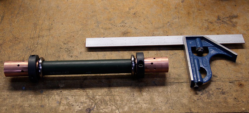
The scale is 12 inches / ≈ 30.5 cm long.
I ought to find myself some thicker copper pipe. This stuff is 'schedule L' pipe, with a nominal bore of 1.025". Note how the pipe is bent inward by the clamps to meet the 1.00" OD of the resistor terminals.
There is a thicker series of copper pipe - 'schedule K' - which has a nominal bore of .995". It should mate more smoothly than the L, and if necessary, I can turn out the ID a few thousandths and still have a thicker wall.
Four more slits need to be made in the outer ends of the copper pipe, so as to receive brass inserts which will connect to the switch at one end, and the outer return casing at the other end, subject to my whims and availability of parts.
The switch housing requires 5" ID copper DWV pipe which is available but annoyingly expensive. I need a short piece for this rig, and a long piece (5 or 6 feet) for the big Marx generator.
Subscribe to:
Posts (Atom)


 Posts