I will be testing with a very small capacitor at first, to try to characterize the switch's behavior, so the big copper hardware won't actually be necessary for a while yet, but it made sense to me to get the difficult work done first.
Have I mentioned that I am not especially fond of machining dead-soft (ETP, which is to say, high conductivity) copper? It tends to bind tools, snapping them, if you aren't careful. I wasn't careful today, so I snapped a small drill bit off in a piece with a lot of time in it. After cooling off, I realized that the hole was nearly through, so I could punch the broken piece of bit through the bottom of the hole. Fortunately, it wasn't a blind hole, or I'd have been well and truly fucked. The bit broke off below the surface. All's well that ends well.
In the fuzzy phonecam image below, you can see that I have added several things...

First, the copper blivets added to the end caps are for connections. The left end blivet has been machined to fit the inside radius of a copper socket which mounts to the capacitor hot stud. After sliding into said socket, the mating surfaces are clamped with three 1/4-20 button-head cap screws (not seen in today's pics because I can't find the damned things, may have to order more) to get adequate (er, it is to be fervently hoped) pressure on the mating surfaces.
The curvature of the two surfaces was made the same. I would have done it differently if I weren't salvaging bits of copper. Copper is expensive. It's REALLY expensive if you don't have bending tools and just decide to arbitrarily machine away everything from a billet that isn't the part you want. I try not to be TOO outrageously wasteful. Have I mentioned that I hate machining copper?
Also visible is the new trigger connector. I am rather proud of that bit of silliness. It is a short piece of the same Delrin™ stock from which the tie-rods were cut, machined on each end to fit the ODs of two tie-rods, thus trapping its ends between them.
I would like to take this moment to say that I love machining Delrin as much or more than I hate machining copper. It's lovely stuff as an engineering resin it's nearly ideal except for acid resistance and a few other edge conditions.
The side facing the axis of the switch has been machined with a curved relief to accommodate the OD of the switch housing, and a slot to accommodate the trigger plane electrode has been milled. That slot incidentally prevents the connection holder from sliding on the tie rods. After the switch is assembled (not unlike a puzzle box, it must be done in a specific sequence) a short length of 8-32 brass rod is threaded into the connection holder, and a corona nut (the brass ball) is added to suppress corona.
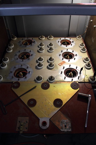
Here is the switch in the process of being test-mounted on one of the six pulse capacitors:

The bolt-terminal of the capacitor is about two inches below that top aluminum plate in the foreground, which is why the copper "socket" is necessary.
That plate was the after-switch "output" plate in the original configuration. For testing this switch it will not be used, and the other capacitors will remain shorted and disconnected from the test setup. For those just joining us, I am using one capacitor out of the six which are in this big pulser system I've got.
The cylindrical housings in the background originally housed ignitrons - one for each capacitor. Now the housings are being used solely to clamp copper connection straps to the top plate - the switching will be done with a single device with all six caps bused together in parallel. This image may clarify matters.
If you're wondering, each cap in the pulser is 60uF, rated for 10,000V charge, 40nH self-inductance, 60kA (or a bit more, I'm still digging) max, and get this - 75% voltage reversal at a discharge frequency of 15kHz. Bused together, capacitor inductances reduce to 6.7nH. Eliminating the ignitrons and the current loop of their housings eliminated another 29 nH of wasted inductance. It'll be a real bang-zoom when all is said and done.
The next part I'll be fabricating (uh, right after I finish designing it) is the test load - a water resistor. Because essentially all of the power of a test shot is dissipated in the load resistor, and since we're talking up to 3,000 joules of stored energy in the big caps, the test resistor must be capable of absorbing all of that energy without getting warm enough to boil the electrolyte. It must also be of reasonable volume and dimensions so as to have low inductance. The resistance is varied by changing the concentration of copper sulfate dissolved in the solution between the contacts. Contact electrodes are brass, and housing may be nearly any plastic. For making connections where some resistance is wanted, long lengths of vinyl hose are frequently used for these resistors. Have a look at this photo of the Marx generators for the Aurora Pulsed Radiation Simulator (sadly, only a memory now) and you'll see some examples.
Once the test load is ready, I will first see what kinds of speed I can get at low current shots (100A or so) using the TM-12 trigger generator and (obviously) a much smaller capacitor. I have several caps to choose from, I haven't decided how fancy (ie, low inductance) I want to get with the small tests. I very much doubt the TM-12 is fast enough to achieve distortion triggering, but the low current limit on the commissioning tests should keep damage to electrodes to a minimum if the thing goes cascade/trigatron on me. Mind you, I also want to run this switch in pseudospark commutation mode. We'll see.
After that, it will be a matter of either building the micro-Marx (an adaption of the "Super Saver Mini Marx" developed by D. Platts at LANL) _OR_ getting one of my other trigger generators working. There's a bloody fast VIG on the premises, but I suspect it has a dead krytron inside. :( I have not yet been able to make it go.
I won't test the switch on the big cap until I've got a really good, fast trigger generator. And all of this is prerequisite and learning for when the time comes to make the big railgap switch commute all 3.6C of charge at once. If it fails to go multi-channel even once, I will have to replace its rails. I would really prefer not to do that, even once. I honestly don't know whether it can be operated in pseudospark mode. I have a lot more research and homework to do.
This work was supported by the Joss Research Institute, Laurel MD.


No comments:
Post a Comment