Showing posts with label Pulser. Show all posts

Saturday, April 14, 2012

distortion-triggered switch is (really) ready to test

Tonight, I finished work on the trigger connector hardware and the copper hardware required to mount the switch to the large test capacitor.

I will be testing with a very small capacitor at first, to try to characterize the switch's behavior, so the big copper hardware won't actually be necessary for a while yet, but it made sense to me to get the difficult work done first.

Have I mentioned that I am not especially fond of machining dead-soft (ETP, which is to say, high conductivity) copper? It tends to bind tools, snapping them, if you aren't careful. I wasn't careful today, so I snapped a small drill bit off in a piece with a lot of time in it. After cooling off, I realized that the hole was nearly through, so I could punch the broken piece of bit through the bottom of the hole. Fortunately, it wasn't a blind hole, or I'd have been well and truly fucked. The bit broke off below the surface. All's well that ends well.

In the fuzzy phonecam image below, you can see that I have added several things...

ready-to-test-1.jpg

First, the copper blivets added to the end caps are for connections. The left end blivet has been machined to fit the inside radius of a copper socket which mounts to the capacitor hot stud. After sliding into said socket, the mating surfaces are clamped with three 1/4-20 button-head cap screws (not seen in today's pics because I can't find the damned things, may have to order more) to get adequate (er, it is to be fervently hoped) pressure on the mating surfaces.

The curvature of the two surfaces was made the same. I would have done it differently if I weren't salvaging bits of copper. Copper is expensive. It's REALLY expensive if you don't have bending tools and just decide to arbitrarily machine away everything from a billet that isn't the part you want. I try not to be TOO outrageously wasteful. Have I mentioned that I hate machining copper?

Also visible is the new trigger connector. I am rather proud of that bit of silliness. It is a short piece of the same Delrin™ stock from which the tie-rods were cut, machined on each end to fit the ODs of two tie-rods, thus trapping its ends between them.

I would like to take this moment to say that I love machining Delrin as much or more than I hate machining copper. It's lovely stuff as an engineering resin it's nearly ideal except for acid resistance and a few other edge conditions.

The side facing the axis of the switch has been machined with a curved relief to accommodate the OD of the switch housing, and a slot to accommodate the trigger plane electrode has been milled. That slot incidentally prevents the connection holder from sliding on the tie rods. After the switch is assembled (not unlike a puzzle box, it must be done in a specific sequence) a short length of 8-32 brass rod is threaded into the connection holder, and a corona nut (the brass ball) is added to suppress corona.

Here is the switch in the process of being test-mounted on one of the six pulse capacitors:

mounting_on_capacitor.jpg

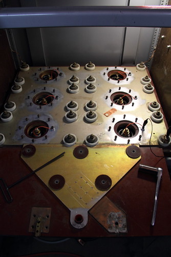
The bolt-terminal of the capacitor is about two inches below that top aluminum plate in the foreground, which is why the copper "socket" is necessary.

That plate was the after-switch "output" plate in the original configuration. For testing this switch it will not be used, and the other capacitors will remain shorted and disconnected from the test setup. For those just joining us, I am using one capacitor out of the six which are in this big pulser system I've got.

The cylindrical housings in the background originally housed ignitrons - one for each capacitor. Now the housings are being used solely to clamp copper connection straps to the top plate - the switching will be done with a single device with all six caps bused together in parallel. This image may clarify matters.

If you're wondering, each cap in the pulser is 60uF, rated for 10,000V charge, 40nH self-inductance, 60kA (or a bit more, I'm still digging) max, and get this - 75% voltage reversal at a discharge frequency of 15kHz. Bused together, capacitor inductances reduce to 6.7nH. Eliminating the ignitrons and the current loop of their housings eliminated another 29 nH of wasted inductance. It'll be a real bang-zoom when all is said and done.

The next part I'll be fabricating (uh, right after I finish designing it) is the test load - a water resistor. Because essentially all of the power of a test shot is dissipated in the load resistor, and since we're talking up to 3,000 joules of stored energy in the big caps, the test resistor must be capable of absorbing all of that energy without getting warm enough to boil the electrolyte. It must also be of reasonable volume and dimensions so as to have low inductance. The resistance is varied by changing the concentration of copper sulfate dissolved in the solution between the contacts. Contact electrodes are brass, and housing may be nearly any plastic. For making connections where some resistance is wanted, long lengths of vinyl hose are frequently used for these resistors. Have a look at this photo of the Marx generators for the Aurora Pulsed Radiation Simulator (sadly, only a memory now) and you'll see some examples.

Once the test load is ready, I will first see what kinds of speed I can get at low current shots (100A or so) using the TM-12 trigger generator and (obviously) a much smaller capacitor. I have several caps to choose from, I haven't decided how fancy (ie, low inductance) I want to get with the small tests. I very much doubt the TM-12 is fast enough to achieve distortion triggering, but the low current limit on the commissioning tests should keep damage to electrodes to a minimum if the thing goes cascade/trigatron on me. Mind you, I also want to run this switch in pseudospark commutation mode. We'll see.

After that, it will be a matter of either building the micro-Marx (an adaption of the "Super Saver Mini Marx" developed by D. Platts at LANL) _OR_ getting one of my other trigger generators working. There's a bloody fast VIG on the premises, but I suspect it has a dead krytron inside. :( I have not yet been able to make it go.

I won't test the switch on the big cap until I've got a really good, fast trigger generator. And all of this is prerequisite and learning for when the time comes to make the big railgap switch commute all 3.6C of charge at once. If it fails to go multi-channel even once, I will have to replace its rails. I would really prefer not to do that, even once. I honestly don't know whether it can be operated in pseudospark mode. I have a lot more research and homework to do.

This work was supported by the Joss Research Institute, Laurel MD.

Monday, March 26, 2012

tooling progress (mill)

A great many projects are waiting for the mill to return to service. I have news about that.

The new phase converter arrived a while back. I've had it mostly-wired up for a week. I've been
er, not well, and also busy as f__k, and so I didn't really think my purchases through. So I still
don't have every thing I need to make it all go. I do have all but one thing, however, and it will
arrive tomorrow afternoon. That one thing is a 3-phase, 4-pole twist-lock connector that I
didin't happen to have on hand. Everything else is in place. When it arrives it will be a matter
of 20 minutes to be online.

Herewith an aside on the futility of saving good quality useful parts for a rainy day:
I have a boat-load of twist-lock connectors of all sorts - recessed inlets and panel mount outlets,
cord connectors, conventional outlets, and more, all for various voltages, currents, phases, et-
bloody-ceteras. And every time I have need such a thing in the past ten years, I have gone through
that collection, and literally nine times out of ten (probably more like 99 in a 100) I have come up
empty handed. The percentages do not make the space taken up (not to mention the capital
value) of them just sitting around here. So I am going to sell every twist-lock and similar power
connector I have (which is a lot, I assure you) on eBay and make a whole bunch of money to re-pay
my recently-raped hobby fund a little, even if I blow them out the door at bargain basement prices
as I intend to do.

I also ran out of money, through some serious miscommunication and well, never mind that.
That's being corrected.

So, by the next time I can find or make some free time in between self-schooling and work, I will
be able to make some parts for the Mad Scientists Light Switch, the triggered spark gap switch,
and so forth and so on.

Monday, February 21, 2011

playing with arc-flash for fun and profit

I worked on the big pulser (for the railgun) over the weekend.

 Lately, job #1 has been to figure out a way to connect the capacitors to the "hot" collector plate.  The means had to be inexpensive, reasonably low effort, and capable of handling the full 60,000 amps from each capacitor.

 The arrangement I am trying first is to clamp four soft copper straps to the capacitor's bolt terminal with a nut, and clamp the opposite ends under the bolt rings of the old ignitron housings.  The rest of the housing won't carry current.  Some nice low-rise clamping rings would be better, but I don't feel a pressing need to make six of them (with eight holes each, ugh) right this minute.

 I made the straps and installed them yesterday.  This involved cutting out forty-eight 1" x 4" x .030" straps from copper sheet (with sheet metal sheers), removing all the corners and sharp edges on the belt sander, and punching forty-eight half-inch holes near one end of each strap.

 After that, I felt an urge to know the leakage rate of the capacitors.  I decided to perform a "megger" (a high voltage insulation tester) test on all six caps.  Now meggers, by their nature, typically put a fair mount of voltage across the unknown.  My instrument, an old Genrad unit, puts out anywhere from 100V to 500V DC.

 Then, before I could start with the measurements, I had to figure out how I would safely discharge the cap bank after it had been charged by the megger.

Step the first was to wind half a dozen turns in my test leads onto some big ferrites.  That should, in theory, keep the hash from the arc out of the detector circuitry of the megger.  I would disconnect it by hand before shorting the bank if I trusted my gloves, but I don't.  Anybody out there have a set of lineman's (Class 2 or 3) gloves in test-passing condition that they don't want?

Step two was to don rubber gloves, leather gloves, face shield, and ear muffs.

 I got my measurement on the low range (100 V) and decided to take measurements at all the other ranges too.  I discharged the caps after each measurement.  I used a "chicken stick" (insulating shorting stick with copper bar at one end) and an extra little bit of brass lying on the top of the collector plate to strike the arcs to, so the collector plate wouldn't get too badly torn up.

 At 100 volts, the 'pop' was impressive, but one does not need hearing protection.  A modern firecracker is louder.  At 200 volts, I decided the hearing protection was a good idea after all.  At 400 volts, I worried what the neighbors might be thinking.

 Note that these are 10,000 volt caps.  So I was playing with 4% of the total energy this cap bank can store.  I won't lie: when this machine lets go with a full charge, I don't want to be in the same room with it. Fortunately I won't have to.  I have a nice concrete block wall separating my workshop from the rest of the garage.  With that and the remote control panel I'm building, we ought to be golden.

 In reality, we don't want this (a short circuit discharge) to happen at any voltage.  Without any significant inductance or resistance for a load, the very high currents and high voltage reversal caused by high frequency ringing (since the "load" inductance is so small) stress the dielectric in the caps rather badly.  It is to be avoided.  These caps don't grow on trees.  Ordinarily, when the caps need to be discharged (either to remove residual charge at the end of a shot, or due to an aborted shot) the caps are drained more slowly (and safely) by a large bank of power resistors connected to the cap bank through a pair of high voltage relays.

 This is also why I'm testing insulation and clearances to the cabinet and the like.  I do not want an uncontrolled arc happening out in the open.  Aside from the obvious undesirability and damage, it will also be EXTREMELY LOUD.  We're talking broken-windows-loud.  Under normal operating conditions, I expect most of the energy to be absorbed or muffled in various ways.  In fact, I am going to rather a lot of effort to ensure that happens.

 Figuratively speaking, I have in the past had the local villagers light torches, take up pitch-forks, and storm my castle because I frightened them. News media, emergency services, and attorneys were involved.  So, let's just say I am not comfortable allowing extremely loud noises to escape from my property these days.

 Oh, and I hope to have the shop's old rolling door finally ripped out and replaced with a wall before the first gun firings take place.  That should cut down on the blast noise a LOT.

After doing the above, I decided I really need to do a proof test on each individual capacitor, and that means disassembling everything I assembled over the weekend.  Well, to be honest, I had other reasons for doing that too.  I need to do a proof test on the collector stack, and THAT has to be done with the capacitors disconnected (but with the stack still mounted on the caps) for what I hope is an obvious reason.

Photos to come later.

PS: I often forget what I've described and what I have not.  It occurs to me that I have not described the capacitor bank high current connections, which I've been referring to above as "the collector stack" so I'll do that now.  The capacitors I have are very early pulse caps using 1960s technology.  They are set up for relatively low inductance connections, although improvements have been made in pulse cap design since these were made.  The capacitor connections are made between the case and a single 1/2-13 brass bolt located in the center of a round, convoluted, hard rubber insulator.  The return connections to the case are made to four brass blocks soldered to the corners of the case.  Threaded holes are provided in said blocks to accept 3/8 brass studs.

To minimize stray inductance, the six capacitors are bussed together with aluminum plates separated by a thin layer of strong insulating material.  The ground/return plate sits directly on the capacitors' ground return blocks.  It has six holes about 4" across to provide clearance for the high voltage connections.  A 1/2" thick plate (could be different material, and thinner) of phenolic-linen laminate goes on top of that. It also has big holes to clear the high voltage connections.  The "hot" or output plate has big holes too, but they are surrounded by rings of eight 1/4-20 threaded holes so that "something" can be connected there. Originally that "something" was an ignitron on top of each capacitor, which sat inside of a coaxial housing which connected to those rings of holes.

I am still using those housings and the original connections for my new connections, only because they are handy and they eliminate - for now - the need to make a whole bunch of new parts.

Friday, February 18, 2011

Don't Put Your Tongue On That Capacitor, You Don't Know Where It's Been!

 Lately, because the lack of a mill has back-burnered the final bits and pieces for my Mad Scientist Light Switch, I've been working on the railgun project instead.  From the very beginning, one of my philosophies for this project was that I was going to everything right.  Because time after time, I had seen other amateur railguns which were almost right in most respects, but wherein the builder got one or two crucial details wrong, and it hurt them. The details really do matter, especially when you're trying to take something which works better at large scales and scale it down.

 I've been thinking a lot about safety.  It's one of those details that a lot of a amateur mad scientists don't think about much.  Honestly, it astonishes me that only a small handful of amateurs have killed themselves working with Tesla coils or big pulse caps.  And I think I've had just about all the second chances with high voltage and lasers and explosives that the fates are likely to grant me. I'm going to try to avoid unplanned excitement for a while.

 Government labs are different.  They care about safety, and they spend a lot of money on it.  PhDs don't grow on trees.  But sometimes even smart people miss a possibility and something bad happens.  I shall describe one such incident in hopes that we'll all learn from it.

 This is entirely from memory, because I can't find the paper in which it is described.  I do have a dead-trees copy somewhere in a box in the basement. Therefore, if I find that or (an online) copy, I'll correct any errors I make and point to a copy you can read.

 Back in the 1950s, the biggest homopolar generator in history (so far) had recently been completed at Australia National University.  And it wasn't long before this 500 MJ monster was connected to a new railgun.  Now railguns want a lot of current, and they have a fair amount of voltage drop across the muzzle- several kilovolts in the plasma armature devices that were in vogue back then.  That's a problem if you're using an HPG for your power supply, since they are great at putting out a lot of current into a dead short, but they aren't good at developing much voltage. So, back then, the standard method was to do pulse compression, much as we do today for high powered pulsed-power projects.  They would discharge the HPG into an inductive transmission line which had the railgun connected to the other end.  Then they'd use a series of short circuiting or opening switches to compress the magnetic field of the line, causing the voltage to soar during the pulse.

 The devices used had to be very fast, and had to handle millions of amperes.  They included special fuses, exotic circuit breakers, and mechanical switches driven by high explosives.

 During preparations for one shot, a heavy equipment cart with metal wheels was rolled over a hydraulic hose which provided high pressure oil to the bearings of the HPG. No apparent damage was caused, and nobody thought anything of it until later. That was because there was no pressure on the hose. But the hose HAD been damaged, and a tiny leak had been created.

 All was made ready in the run room, personnel left, and the heavy steel door between the gun room and the control room was closed and locked.

 Various power supplies were charged, trigger generators armed, and then the HPG was spun up to speed, which included pressurizing the bearings. The high pressure oil leaked out of the supply hose in a very fine mist.  Unknown to the operators, and not visible on the remote cameras, oil vapor was now filling the gun room.

 When the shot was fired, the various plasma clouds and sparks promptly ignited the vapor in the room, causing a significant explosion which blew the heavy steel blast door from its hinges, injuring the technician seated nearest it.

 The point being: ask yourself a LOT of questions that begin, "what would happen if..." before you ever apply power to anything.

 Now I've just completed a 1,000 PSI gas injector system which will pre-accelerate the armature before it reaches the rails. This simple "system" consists of:

• a storage plenum (2" Sch.80 steel pipe + fittings)
• an electrically operated valve with high CV*, or flow capability
• a gauge and utility valves for filling and emptying the plenum without opening the main valve
• coupling plumbing and hardware to fit railgun breach-block

Here's a pic:


Later, after commissioning tests, it will be desirable to place a DeLaval nozzle between main valve and gun breach, to increase gas speed within the gun.

 One of the "gotchas" I discovered recently was in the breachblock assembly, which gives me a way of connecting things to the back end of the gun, such as a high pressure injector system.  The breach closure must be designed so it can be easily removed for cleaning, inspection, disassembly, and re-loading.

 The breachblock assembly must contain 1,000 PSI of gas pressure.  Further, the plug which closes it is 2" in diameter, so now we're seeing 3,140 pounds of force on the breach-plug.  Don't worry, I designed it to take that and then some.  It's massive.  But that was only the forces within the two-part system of breach-plate and breach plug-plate.

 Then I looked at the interface -- and more significantly, the gas seal -- between the breach plate and the rest of the gun.  What if my original seal design -- with two seals, one being a "backup" -- would fail at the inner seal?  The additional exposed area inside the outer seal raises the force on the breach plate to about 20,000 pounds-force. I'm not sure I want to load the bolts that much. So I eliminated the outer seal! Now if the single remaining seal fails, all that happens is that gas at design pressure leaks out undramatically.  I don't expect that inner seal to fail, but no one ever expects the Spanish Inquisition!

The big pulser-without-a-name had been designed with interlocks originally, but they were all defeated, broken, or missing by the time it came to me.  I will of course be repairing / replacing them.  I need to sit down at some point and work through the entire sequence / time-line of a shot preparation, firing, and safing.  Eventually, I'll probably even have a check list and some rotating beacons, because those things not only improve safety, they're just good fun for any red-blooded geek.

"Arming test lights on, one through four?"

"Arming test lights on, one through four!"

Ya know, all this work would be a lot easier if I had a team and a budget.  Sure wish I'd gone to school.

_________________________________________
* (CV = valve coefficient, which equates to flow restriction through the valve. In COTS valves, it is usually driven by the valve's smallest opening, typically the valve seat)

Monday, January 31, 2011

The Beast With No Name

Around 1995 or so, I received a call from a good friend, asking me if I might be interested in a very large and very heavy high voltage capacitor bank -- capacitors specifically intended for pulse discharge duty -- with its own charging and switching circuitry; in short a complete, turn-key pulsed discharge machine. I immediately said, "yes" and then wondered where I was going to put it since I was living in an apartment at the time.


The thing was immense, weighing just a bit shy of 2,000 pounds. It consisted of two 28" wide rack panel cabinets mounted on a steel skid with four groaning casters. The shorter of the two contained the high voltage power supply, ancillary power supplies for things like control voltages, and a bit of relay control "logic" to interact with operator input and interlocks while enforcing safety rules.


The larger of the two cabinets contained the pulse capacitors (six), a parallel plate current collector stack (nice low inductance design), six ignitrons (one on each cap) in coaxial housings, as well as a bunch of other hulking heavy duty high voltage equipment to trigger the ignitrons, including a nice glass hydrogen thyratron.

This thing was designed in the 1960s and built in the 1970s. It was moderately cutting edge stuff for its time. The company wanted to investigate industrial applications for pulsed power including well frac'ing, and magnetic metal forming. Fortunately, all of the designer's personal notes and sketches, as well as notes from later techs who worked on the machine to rehabilitate it in the early 1990s, were saved and given to me when I got the thing. That has been incredibly valuable.

What happened is that the company's focus had moved on and narrowed - they had made interesting strides in metrology. They were being purchased by another company already famous in the business. They needed to clean house, and SOMEHOW, that two thousand pound white elephant had to go. If I could move it, I could have it. It sat for a bit while I figured out where in the hell I was going to put it, and how. The owner of the company was awfully patient with me.

Well, I had a sort of professor emeritus status with the entity which at that time was right in the middle of morphing from The Dream Park Corporation (bankrupt) into The Diabolic Company. Said organization had just moved into an IMMENSE building which had previously held a K-Mart. I asked, and I was basically told, "any place that won't interfere with the haunted house operation, knock yourself out".

The short version is: I stashed it there.

I got some friends to help me move it.

And we dropped it. But that's a story not terribly relevant here and now.

The astonishing thing was, we didn't do it any harm - er, probably. There was a little sheet metal damage, but it had slid down and landed with a jolt, we didn't really drop it off the dock. The only thing affected was the ignitrons. You see, ignitrons are finicky beasts. They have their advantages (they can switch HUGE charge transfers) but one of their idiosyncrasies is that once they have been used in crowbar or capacitor discharge duty, it is crucial that they not be moved or jarred. When ignitrons ares used in those high-wear modes, the structure which supports the ignitor electrode over the pool of mercury becomes very fragile. And shifting or sloshing of that pool of mercury is likely to damage the ignitor, rending the tube inoperative. True story.

The way we were rolling that thing around the lab and bumping it over doorways to get to the dock, all six of those tubes were toast before we ever got around to dropping it off the dock. Of course, I didn't find that out until later. About the same time in fact that I found out replacement ignitrons cost $1,500. Each.

Not having a spare nine grand burning a hole in my pocket, I decided to use another means of switching. I got rid of the ignitrons to a friend who was collecting mercury anyway. Don't ask. One less hazardous materials disposal pickup (we have an awesome trash department) for me to deal with.

Meanwhile, I needed a way to move this beat around without a Class IV forklift. While I still had the shop and lab space at DiaboliCo's haunted house building, I took to rebuilding it. I removed the power supply and its cabinet, disassembled the ignitron housings, and plate stack, removed the cabinet, and eventually unstacked the six pulse caps. They weigh about 150 pounds each. I'm guessing. It I ever weighed them, I've lost it, though I ought to have the shipping weight in my folder. Anyway. Then I split the big steel skid the whole thing had been mounted on, with a torch. I added more steel, and two new casters, and I had two skids. Then everything was reassembled onto those. Mind you, with a few rare exceptions when I was in a hurry and people were around to help, I was doing most of this alone, all Leedskalnin-style, with levers, blocks, ropes, pulleys and the convenient architectures of the building.

After that, the machine followed me around, all 2,000 pounds of it, through two moves, and has been sitting in my workshop alongside my collection of other Large Heavy Objects, waiting for me to figure out which way to go with it. In the mean time, I've been learning about high speed and high current switching devices. Since I acquire the thing, I've learned a GREAT DEAL.

I've been given one type of switch - which I've yet to fire, tho I am inching closer - and I've designed and built another type - which I've also yet to fire. I'm inching closer to that event too.

Stupid mill.

While the mill has been down I've been working on the parts of the long-stalled railgun project. The parts that don't require the mill, that is. That would including the pulser, or as the previous owner called it, "The Banger" (as far as I am concerned, it still doesn't have the great name it should, yet). From what he told me of their insane escapades, I bet every one of them needed hearing aids. Exploding wires are louder than gun shots, kids.

The first thing I did was excavate the machine itself from a mound of boxes. The new effort provoked a quick round of shop-cleaning this weekend. The second thing I did was remove all of the ancillary parts that were necessary for triggering the ignitrons, about 50 pounds of transformer, capacitors, rectifier, and blah-blah oh yes and a nice thyratron.

I ought to describe how the thing worked before I got my grubby mitts on it and tore half its guts out. It'll be illustrative of how things often go in the pulsed power world. Say you've got a whacking huge amount of energy you want to apply to load with a whacking huge switch. Trouble is, whacking huge switches by their very nature, tend to require a whacking huge something to activate them. Might be a huge pulse of electricity. Or perhaps some compressed air. Explosives are often used. Not kidding. So you come up with this pretty substantial trigger pulse to trigger your whacking huge switch. That pretty substantial trigger energy has to be switched by a substantial switch. The substantial switch needs at least an adequate switch, and so on, finally ending at the big red, jolly, candy-like button on your control panel.

So, this is how this particular machine was originally designed to work:

1. The operator sets the voltage at which they want the machine to fire on a dial (a Simpson relay meter).

2. The operator places the work in the fixture, which is already connected to the machine's output bus.

3. The operator presses the 'Start' button, and I would presume, gets the hell away from there.

4. The machine charges, slowly I assume, and when the meter needle reaches the aforementioned setpoint, the machine discharges in the following sequence:

5. because the Simpson meter contacts aren't good for any current at all, when they make contact, they are used to control another, ordinary industrial control relay.

6. that relay's contacts apply a voltage to a control grid in a pentode

7. the pentode turns on and dumps the charge of a small high voltage capacitor through the primary of a pulse transformer

8. the secondary of the pulse transformer delivers a small high voltage pulse to the

9. hydrogen thyratron located in the capacitor cabinet, which turns on and connects one side of six beefy high voltage capacitors to ground, dumping their charge through the ignitor electrodes of six ignitrons. Inside each ignitron, 100 joules of energy vaporizes a small amount of the mercury in the pool into the vacuum of the tube. The mercury vapor connects the anode and the cathode, turning on the ignitron tube until there is no more current to keep the vapor hot. Functionally, it behaves a lot like an SCR.

Seems a bit complicated, don't it? But that's the way it is. I'm going to try to do this with more sophisticated (and more importantly, obtainable) components, but there is still (and will always be) a long series of steps between you and the big drama. That's another good point worth raising - isolation. You don't want any kind of freak fault to allow the main store energy to get out into places it doesn't belong, such as remote control pendants. That would be bad.

Oh yeah, it came with a crude remote control pendant. I'm already working on a more sexy remote control, uh, "pendant". Well, panel anyway. Okay really, it's more of a box. With a panel that mounts inside the box. Like a miniature rack, sort of. Only with storage inside the lid. I'll try not to let it get any bigger. Also, it's long term project, and won't be done before the pulser-with-no-name is in operation.

Speaking of names, I could use one. It's an idiosyncrasy of mine - I like to name things. If you've got any clever ideas, leave me a comment or something.