 I saw something similar to this arrangement in a commercial generator, but that one had more space between the stages. Note that the inter-stage insulator forms an additional small capacitor across each stage gap. As each stage erects, this additional capacitance must be charged before the gap overvolts. With care in spacing, dielectric material, and some attention to field shaping at the edges, that capacitance may be sufficiently low that the additional stages-per-unit-length of generator housing make it a worth while dodge. I need to go on a paper-reading bender again, see if anyone has done something similar.
Showing posts with label Marx Generators. Show all posts
Showing posts with label Marx Generators. Show all posts
Friday, June 15, 2012
somewhat different Marx generator configuration
I saw something similar to this arrangement in a commercial generator, but that one had more space between the stages. Note that the inter-stage insulator forms an additional small capacitor across each stage gap. As each stage erects, this additional capacitance must be charged before the gap overvolts. With care in spacing, dielectric material, and some attention to field shaping at the edges, that capacitance may be sufficiently low that the additional stages-per-unit-length of generator housing make it a worth while dodge. I need to go on a paper-reading bender again, see if anyone has done something similar.
Monday, June 11, 2012
fast Marx generator progress
Since one of the things I need to test the recently completed switch is a very fast, very high voltage trigger source; and since I was already working on a fast coaxial Marx anyway, it just became a high priority again. As a reminder, "fast" in this case means (hopefully) much less than 1uS and hopefully << 10nS; and "high voltage" means not less than 60kV, although I am hoping to stuff enough stages into the housing I have on hand to allow for 80kV or 100kV. If I can find more caps with appropriate specs before I begin final construction, I might even manage 100kV from only eight stages. Stuffing more than eight stages into a housing only 4" x 19" is proving problematical. If I unexpectedly obtain longer housing and insulator tubes before I begin assembly, I'll think about changing my plans.
I accomplished a fair amount of work on the housing this weekend. Because I am not yet set up to weld aluminum, I am still making the bloody housing out of copper and brass which can be silver-soldered to get a flange onto the ground end at the very least. Given that this is a voltage, high impedance, low current device, it doesn't NEED to be made out of those materials, I'm simply working with what is most readily available and has the lowest cost - for me, given the resources at my disposal - to achieve.
I've nearly finished the closure flange for the ground end, through which pass two gas ports (gas & relief), two SHV connectors for charging voltage and trigger, and possibly a small but high quality pressure gauge if I can find room.
I would like to have flanges on both ends, but the amount of effort and cost to make another identical flange for the hot end seems prohibitive for now.
I accomplished a fair amount of work on the housing this weekend. Because I am not yet set up to weld aluminum, I am still making the bloody housing out of copper and brass which can be silver-soldered to get a flange onto the ground end at the very least. Given that this is a voltage, high impedance, low current device, it doesn't NEED to be made out of those materials, I'm simply working with what is most readily available and has the lowest cost - for me, given the resources at my disposal - to achieve.
I've nearly finished the closure flange for the ground end, through which pass two gas ports (gas & relief), two SHV connectors for charging voltage and trigger, and possibly a small but high quality pressure gauge if I can find room.
I would like to have flanges on both ends, but the amount of effort and cost to make another identical flange for the hot end seems prohibitive for now.
Sunday, January 2, 2011
Dr. Carl E. Baum dies
Dr. Carl E. Baum, founder of the Summa Foundation and one of the shining lights of pulsed power research, died December 2, 2010 at the age of 71. I've mentioned his name before. Among many other achievements, he is notable for being the designer of the famed Trestle (ATLAS-1) EMP simulator at Kirtland AFB, New Mexico.
Carl E. Baum was born in Binghamton, New York, on February 6, 1940. He received his B.S. (with honors), M.S., and Ph.D. degrees in electrical engineering from the California Institute of Technology, Pasadena, in 1962, 1963, and 1969.
He received the degree of Doktoringenieurs Ehren halber (Dr.-Ing. E.h.) (Doctor of Enginering honoris causa) from the Otto-van-Guericke-University Magdeburg, Germany, in 2004.
He was stationed at the Air Force Research Laboratory, Directed Energy Directorate (formerly Phillips Laboratory, formerly Air Force Weapons Laboratory), Kirtland AFB, Albuquerque, NM, from 1963 to 1967 and from 1968 to 1971.
From 1971-2005 he served as a civil servant with the of Senior Scientist at the Air Force Research Laboratory. Since 2005 he has been a distinguished research professor at the University of New Mexico, Department of Electrical and Computer Engineering.
You would be hard-pressed to find a paper on electromagnetic pulse or ultrawideband high power signal generation without his name on it somewhere.
You may read his full obituary here.
Carl E. Baum was born in Binghamton, New York, on February 6, 1940. He received his B.S. (with honors), M.S., and Ph.D. degrees in electrical engineering from the California Institute of Technology, Pasadena, in 1962, 1963, and 1969.
He received the degree of Doktoringenieurs Ehren halber (Dr.-Ing. E.h.) (Doctor of Enginering honoris causa) from the Otto-van-Guericke-University Magdeburg, Germany, in 2004.
He was stationed at the Air Force Research Laboratory, Directed Energy Directorate (formerly Phillips Laboratory, formerly Air Force Weapons Laboratory), Kirtland AFB, Albuquerque, NM, from 1963 to 1967 and from 1968 to 1971.
From 1971-2005 he served as a civil servant with the of Senior Scientist at the Air Force Research Laboratory. Since 2005 he has been a distinguished research professor at the University of New Mexico, Department of Electrical and Computer Engineering.
You would be hard-pressed to find a paper on electromagnetic pulse or ultrawideband high power signal generation without his name on it somewhere.
You may read his full obituary here.
Wednesday, December 29, 2010
current, power, energy
Since my last post, I have repaired the part I thought I'd ruined, and have made further progress on the Mad Scientist Light Switch. Nothing worth showing you just yet however.
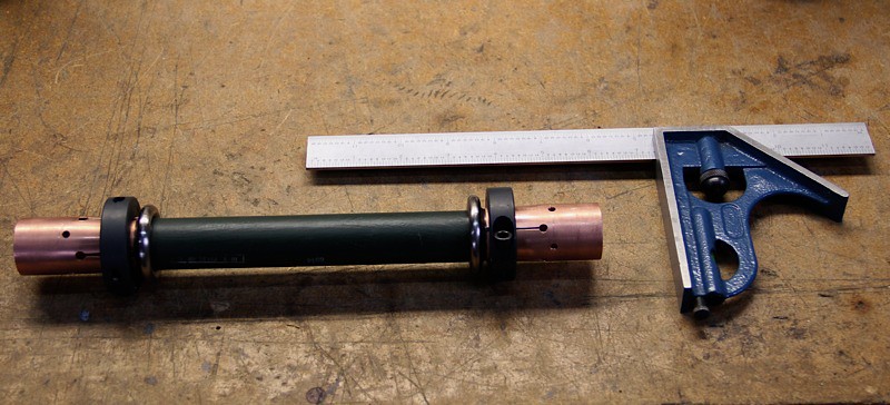
I've also inched forward a bit in work toward commissioning tests of my triggered spark gap switch. One of the things I'll need to test and characterize it is a series of dummy loads of various values, all very low inductance, and capable of absorbing around 3kJ in a short pulse.
The resistors I can either make, or in some cases like that shown here, I may get lucky and find something commercial that will serve.
To use any such resistors, I've got to have a way to connect them to the switch, and the switch to the capacitor and so forth. The connections will have to pass a series of increasingly high current test shots, stepping up by orders of magnitude. Here's my first pass at a basic high current, low-inductance connector for the resistor:

The scale is 12 inches / ≈ 30.5 cm long.
I ought to find myself some thicker copper pipe. This stuff is 'schedule L' pipe, with a nominal bore of 1.025". Note how the pipe is bent inward by the clamps to meet the 1.00" OD of the resistor terminals.
There is a thicker series of copper pipe - 'schedule K' - which has a nominal bore of .995". It should mate more smoothly than the L, and if necessary, I can turn out the ID a few thousandths and still have a thicker wall.
Four more slits need to be made in the outer ends of the copper pipe, so as to receive brass inserts which will connect to the switch at one end, and the outer return casing at the other end, subject to my whims and availability of parts.
The switch housing requires 5" ID copper DWV pipe which is available but annoyingly expensive. I need a short piece for this rig, and a long piece (5 or 6 feet) for the big Marx generator.
I've also inched forward a bit in work toward commissioning tests of my triggered spark gap switch. One of the things I'll need to test and characterize it is a series of dummy loads of various values, all very low inductance, and capable of absorbing around 3kJ in a short pulse.
The resistors I can either make, or in some cases like that shown here, I may get lucky and find something commercial that will serve.
To use any such resistors, I've got to have a way to connect them to the switch, and the switch to the capacitor and so forth. The connections will have to pass a series of increasingly high current test shots, stepping up by orders of magnitude. Here's my first pass at a basic high current, low-inductance connector for the resistor:
The scale is 12 inches / ≈ 30.5 cm long.
I ought to find myself some thicker copper pipe. This stuff is 'schedule L' pipe, with a nominal bore of 1.025". Note how the pipe is bent inward by the clamps to meet the 1.00" OD of the resistor terminals.
There is a thicker series of copper pipe - 'schedule K' - which has a nominal bore of .995". It should mate more smoothly than the L, and if necessary, I can turn out the ID a few thousandths and still have a thicker wall.
Four more slits need to be made in the outer ends of the copper pipe, so as to receive brass inserts which will connect to the switch at one end, and the outer return casing at the other end, subject to my whims and availability of parts.
The switch housing requires 5" ID copper DWV pipe which is available but annoyingly expensive. I need a short piece for this rig, and a long piece (5 or 6 feet) for the big Marx generator.
Wednesday, April 14, 2010
brief status update
Work continues slowly on the mad scientist light switch. Some of the work is rework to fix mistakes, but I'm still pulling ahead slowly. That remains a priority just so I can get all of the parts off of my bench.
I'm also working simultaneously on the micro-Marx generator. I am rapidly gaining respect for the guys who designed the new breed of fast Marx generators in the 60s, 70s, and 80s, because I now realize that every time you want to change one little thing, EVERYTHING else in the system changes. Like Tesla coils, Marx generators look simple as a schematic on paper, but turn out to be surprisingly complex in actual physical design and the calculations required to determine said physical design. The best performing examples are finely tuned devices. I am aware that I'm probably smarter than the average man on the street - tho I'm no genius - but the guys who do this stuff for a living are considerably smarter than I.
I'm in the process of evaluating two physical layouts for the insert panel which will hold the spark gaps on one side and the caps on the other. The winner will offer the best tradeoff between number of stages which will fit into the available space and self-inductance. I was surprised to notice for the first time a few weeks ago that the design I am working from as a stepping-off point creates a helical current path when the bank erects. I can't help wondering whether that is deliberate or accidental. As near as I can tell, any stray or self inductance in the system is undesirable. Stray capacitance quite the opposite, as it can be used to decrease erection time significantly.
I've also changed the sphere gap size, which required an extensive redesign in SolidWorks and as I still do not have a SolidWorks platform at home I'm limited to working on that task on my lunch hour and after work hours. It's taking a while. Any readers out there feel like donating a semi-modern Windows box for me to use as a CAD (SolidWorks) platform?
I am attempting to learn how to calculate all of the stray inductances and capacitances so as to determine the device's characteristic impedance. I'd like to include such design parameters in my spreadsheet-based "Marx Calculator". Good thing I'm studying calculus this year. At least in theory. Free time seems to be at a minimum lately.
There are some physical machining tasks for the micro-Marx housing and liner which will not change no matter what happens to the innards. I can start on those whenever I have the MSLS done.
So things are happening, they just aren't happening quickly, and I haven't any photogenic progress to show off for the moment. I might be able to post something along those lines near the end of next week. I want to put up some images, notes, and calculations from the micro-marx design I am working on.
I'm also working simultaneously on the micro-Marx generator. I am rapidly gaining respect for the guys who designed the new breed of fast Marx generators in the 60s, 70s, and 80s, because I now realize that every time you want to change one little thing, EVERYTHING else in the system changes. Like Tesla coils, Marx generators look simple as a schematic on paper, but turn out to be surprisingly complex in actual physical design and the calculations required to determine said physical design. The best performing examples are finely tuned devices. I am aware that I'm probably smarter than the average man on the street - tho I'm no genius - but the guys who do this stuff for a living are considerably smarter than I.
I'm in the process of evaluating two physical layouts for the insert panel which will hold the spark gaps on one side and the caps on the other. The winner will offer the best tradeoff between number of stages which will fit into the available space and self-inductance. I was surprised to notice for the first time a few weeks ago that the design I am working from as a stepping-off point creates a helical current path when the bank erects. I can't help wondering whether that is deliberate or accidental. As near as I can tell, any stray or self inductance in the system is undesirable. Stray capacitance quite the opposite, as it can be used to decrease erection time significantly.
I've also changed the sphere gap size, which required an extensive redesign in SolidWorks and as I still do not have a SolidWorks platform at home I'm limited to working on that task on my lunch hour and after work hours. It's taking a while. Any readers out there feel like donating a semi-modern Windows box for me to use as a CAD (SolidWorks) platform?
I am attempting to learn how to calculate all of the stray inductances and capacitances so as to determine the device's characteristic impedance. I'd like to include such design parameters in my spreadsheet-based "Marx Calculator". Good thing I'm studying calculus this year. At least in theory. Free time seems to be at a minimum lately.
There are some physical machining tasks for the micro-Marx housing and liner which will not change no matter what happens to the innards. I can start on those whenever I have the MSLS done.
So things are happening, they just aren't happening quickly, and I haven't any photogenic progress to show off for the moment. I might be able to post something along those lines near the end of next week. I want to put up some images, notes, and calculations from the micro-marx design I am working on.
Friday, April 2, 2010
Fast Micro-Marx Generator revisited
////// EDIT: pretty pictures added 4-2-2010 @ 9:08 AM //////
Eventually, this blog is going to earn me a visit from some three letter agency, I'm sure. That is, in part, why I am blogging about these fun amateur science projects so publicly. So if I disappear suddenly, please do drop an inquiry to the warden of the Thompson Correctional Center, Thompson Ilinois. I understand that's where political prisoners are going to be going soon.
But I digress, as usual.
I've been a bit ... not myself lately, and struggling with various challenges. I haven't accomplished much actual work on any projects (until recently) although I have been slowly setting up certain machining operations and preparing the way for various things to be done when I'm better rested, not stressed out, wide awake, and so forth. There will soon be parts at stake which have many hours of time in them. Fucking them up is not acceptable.
Oh yeah: I swear a lot in this blog, as I am attempting to write in a more chatty tone, and since I swear a lot in real life... there you have it.
I have tattoos also.
I should buy a motorcycle.
Anyway. Today I was obsessed with thoughts of the Fast Micro-Marx Generator, and not ready to proceed on the Mad Scientist Light Switch parts... so I did a lot of thinking when I wasn't having to use my brain to do my job, which was most of the day to be honest. Over my lunch hour, I dug up some papers by various really smart people about spark gaps and clever Marx generator techniques and peaking gaps and so forth and so on. There's a lot to think about for a guy who isn't very strong in math.
When I got home this evening I was ambitious for the first time in weeks, and I set to work. One of the assemblies that makes up the FMMG (cough, get used to it) is the housing which is, incidentally, also the current return and coaxial shield of the Marx Generator. The housing shall be constructed mostly from a length of 4" diameter copper pipe. The ends were saw-cut as I received it, and after cutting a piece close to the final length needed, the ends will need to be made square and circular preparatory to having flanges fitted to each end.
A problem arises: how to turn this pipe. Although I can chuck it in the lathe, it is soft, thin-wall copper and I don't have a way to support the other end.
The answer is a mandrel which can be supported at the far end by the tailstock center, fitted with two disks to support the tubing, one at the headstock end which supports the tube where it is clamped by the chuck. The other disk is fixed to the mandrel an inch or so inside the tail end of the pipe using, oh, three set screws. The OD of the disks are chosen to be only a few thousandths less than the ID of the pipe. Et Voila! The tube is now supported firmly, gripped by the chuck firmly and may be carefully turned. Which reminds me, copper is notorious for being a S.O.B. to machine, I must look up the tips and tricks and figure out what kind of tool I'm going to need. Yay insert tooling!
Tonight, I made the mandrel. It's a piece of thick walled steel tubing (pipe) fitted with inch or so long bushings turned to fit neatly into each end. The pipe had four quarter-inch holes drilled into it. The bushings were welded into place through these holes as well as around the flange left on the end. The the welded ends were annealed with a torch prior to turning. The ends were turned down, center holes were drilled into each end, and it may now be turned between centers. Except since I haven't got the headstock accessories required to do that, I suppose I'll fix one end to the headstock disk with a bunch more set screws. Hooray. I want the disks removable so I can use this for another tool some day.
Anyway, the mandrel proper is finished, but lo and behold, the fucker has a taper - that is, one end is larger in diameter than the other. A fairly significant taper. This means that the center of rotation of my lathe's head stock is not aligned axially with the center of my tail stock. This is annoying, but correctable, by adjusting the tail stock. I'll want to mount up some other hunk of metal rather than carving the walls of my mandrel ever thinner. Harrumph. This is annoying, but not surprising. I've never turned anything long before, so I wouldn't have noticed (although I've suspected for a long time).
After I decided I was done working in the shop, I cleaned up, came inside, had dinner, and then set to working on my Marx generator spreadsheet. I've started a section to help me do the calculations for the distributed capacitance and inductance of all the current paths, some of which are tortuous. If I do this thoroughly and correctly, I should be able to estimate the characteristic impedance of the thing. That will be important to know later.
After I built models in Solidworks, I was dismayed to find that my doorknob capacitors take up quite a lot of room and that I might not be able to fit as many stages (ten) as I'd originally hoped:

That's the current state of my Solidworks model for the Marx bank itself - what I've come to call the "insert" since this is the bit that goes inside the housing. It was nice and tidy and complete, with all of those spheres (the stage gaps) mounted to the panel with screws and a peaking gap design mounted at one end... until I discovered a few things about peaking gaps. Then I had to tear it apart and I haven't had time at work to finish changing the configuration, design, and dimensions. I don't have a machine at home on which I can run Solidworks.
At any rate, I now realize that the output peaking gap has to be a separate assembly with a different gas pressure (and different gas, most likely). Making it a separate unit frees up room inside the Marx housing for another stage. The end with the two holes and an empty space is where the peaking gap was. We are now looking at eight stages with a charge voltage of 10kV, so an erected voltage of 80kV max. Not the 100kV I'd originally been hoping for, but c'est la vie.
The peaking gap, IF it is connected directly to the output of the Marx bank, will steepen the Marx output rise time, as it provides a slight delay ensuring that all stages in the Marx have erected before connecting the output to the load. It is possible to construct special peaking gaps which go from non-conducing to full conducting in extraordinarily short times (pS regime) by using special geometries, gas mix, and pressures versus what's used in the Marx bank.
But there are other clever tricks in the pulsed power business that I am tempted to try. One of them is the intermediate storage transmission line and peaking gap. Funny things happen when you do this right, although the dimensions - especially length - can become inconvenient quickly. Here's a block diagram of how the real pulsed power boffins typically obtain ridiculous peak powers by pulse compression:

Now _if_ (and that is a big 'if') I decide to try such advanced shenanigans, I will have to maintain a constant impedance throughout the entire structure, Marx bank, intermediate store, peaking switch, etc. So it behooveth me to know what the characteristic impedance of my Marx bank is to begin with. Knowing that, I can figure out the necessary scale required to do the more advanced stuff (and see whether it's practical or something I really want to get into). Also, it will enable me to make that peaking gap switch work better, and ultimately, match the output of the pulser to some (still hypothetical) load.
The original purpose of this Marx generator was to generate a fast enough (and high enough voltage) trigger pulse for my distortion-triggered spark gap switch:

A very fast, very high voltage trigger is needed to achieve proper field distortion triggering and hopefully operate the switch in pseudospark commutation mode.
However since I acquired the spiral generator (which I've previously blogged about):

...I'm not sure I need the Marx for that purpose any more. But I do still need to build a small prototype and understand its behavior thoroughly before attempting the larger device that I plan to use for UWB impulse radiating experiments.
Thus, the new tables in the spreadsheet, and many measurements to be taken from 3D models and parts to plug into the spreadsheet formulae.
Over the weekend, I'll probably go back to working on the Mad Scientist Light Switch project.
That's how it goes,
everybody knows.
PS: Watch this space, I'll try to backfill some pictures, after I get them taken, or at least throw in some screengrabs of SolidWorks models.
Eventually, this blog is going to earn me a visit from some three letter agency, I'm sure. That is, in part, why I am blogging about these fun amateur science projects so publicly. So if I disappear suddenly, please do drop an inquiry to the warden of the Thompson Correctional Center, Thompson Ilinois. I understand that's where political prisoners are going to be going soon.
But I digress, as usual.
I've been a bit ... not myself lately, and struggling with various challenges. I haven't accomplished much actual work on any projects (until recently) although I have been slowly setting up certain machining operations and preparing the way for various things to be done when I'm better rested, not stressed out, wide awake, and so forth. There will soon be parts at stake which have many hours of time in them. Fucking them up is not acceptable.
Oh yeah: I swear a lot in this blog, as I am attempting to write in a more chatty tone, and since I swear a lot in real life... there you have it.
I have tattoos also.
I should buy a motorcycle.
Anyway. Today I was obsessed with thoughts of the Fast Micro-Marx Generator, and not ready to proceed on the Mad Scientist Light Switch parts... so I did a lot of thinking when I wasn't having to use my brain to do my job, which was most of the day to be honest. Over my lunch hour, I dug up some papers by various really smart people about spark gaps and clever Marx generator techniques and peaking gaps and so forth and so on. There's a lot to think about for a guy who isn't very strong in math.
When I got home this evening I was ambitious for the first time in weeks, and I set to work. One of the assemblies that makes up the FMMG (cough, get used to it) is the housing which is, incidentally, also the current return and coaxial shield of the Marx Generator. The housing shall be constructed mostly from a length of 4" diameter copper pipe. The ends were saw-cut as I received it, and after cutting a piece close to the final length needed, the ends will need to be made square and circular preparatory to having flanges fitted to each end.
A problem arises: how to turn this pipe. Although I can chuck it in the lathe, it is soft, thin-wall copper and I don't have a way to support the other end.
The answer is a mandrel which can be supported at the far end by the tailstock center, fitted with two disks to support the tubing, one at the headstock end which supports the tube where it is clamped by the chuck. The other disk is fixed to the mandrel an inch or so inside the tail end of the pipe using, oh, three set screws. The OD of the disks are chosen to be only a few thousandths less than the ID of the pipe. Et Voila! The tube is now supported firmly, gripped by the chuck firmly and may be carefully turned. Which reminds me, copper is notorious for being a S.O.B. to machine, I must look up the tips and tricks and figure out what kind of tool I'm going to need. Yay insert tooling!
Tonight, I made the mandrel. It's a piece of thick walled steel tubing (pipe) fitted with inch or so long bushings turned to fit neatly into each end. The pipe had four quarter-inch holes drilled into it. The bushings were welded into place through these holes as well as around the flange left on the end. The the welded ends were annealed with a torch prior to turning. The ends were turned down, center holes were drilled into each end, and it may now be turned between centers. Except since I haven't got the headstock accessories required to do that, I suppose I'll fix one end to the headstock disk with a bunch more set screws. Hooray. I want the disks removable so I can use this for another tool some day.
Anyway, the mandrel proper is finished, but lo and behold, the fucker has a taper - that is, one end is larger in diameter than the other. A fairly significant taper. This means that the center of rotation of my lathe's head stock is not aligned axially with the center of my tail stock. This is annoying, but correctable, by adjusting the tail stock. I'll want to mount up some other hunk of metal rather than carving the walls of my mandrel ever thinner. Harrumph. This is annoying, but not surprising. I've never turned anything long before, so I wouldn't have noticed (although I've suspected for a long time).
After I decided I was done working in the shop, I cleaned up, came inside, had dinner, and then set to working on my Marx generator spreadsheet. I've started a section to help me do the calculations for the distributed capacitance and inductance of all the current paths, some of which are tortuous. If I do this thoroughly and correctly, I should be able to estimate the characteristic impedance of the thing. That will be important to know later.
After I built models in Solidworks, I was dismayed to find that my doorknob capacitors take up quite a lot of room and that I might not be able to fit as many stages (ten) as I'd originally hoped:
That's the current state of my Solidworks model for the Marx bank itself - what I've come to call the "insert" since this is the bit that goes inside the housing. It was nice and tidy and complete, with all of those spheres (the stage gaps) mounted to the panel with screws and a peaking gap design mounted at one end... until I discovered a few things about peaking gaps. Then I had to tear it apart and I haven't had time at work to finish changing the configuration, design, and dimensions. I don't have a machine at home on which I can run Solidworks.
At any rate, I now realize that the output peaking gap has to be a separate assembly with a different gas pressure (and different gas, most likely). Making it a separate unit frees up room inside the Marx housing for another stage. The end with the two holes and an empty space is where the peaking gap was. We are now looking at eight stages with a charge voltage of 10kV, so an erected voltage of 80kV max. Not the 100kV I'd originally been hoping for, but c'est la vie.
The peaking gap, IF it is connected directly to the output of the Marx bank, will steepen the Marx output rise time, as it provides a slight delay ensuring that all stages in the Marx have erected before connecting the output to the load. It is possible to construct special peaking gaps which go from non-conducing to full conducting in extraordinarily short times (pS regime) by using special geometries, gas mix, and pressures versus what's used in the Marx bank.
But there are other clever tricks in the pulsed power business that I am tempted to try. One of them is the intermediate storage transmission line and peaking gap. Funny things happen when you do this right, although the dimensions - especially length - can become inconvenient quickly. Here's a block diagram of how the real pulsed power boffins typically obtain ridiculous peak powers by pulse compression:
Now _if_ (and that is a big 'if') I decide to try such advanced shenanigans, I will have to maintain a constant impedance throughout the entire structure, Marx bank, intermediate store, peaking switch, etc. So it behooveth me to know what the characteristic impedance of my Marx bank is to begin with. Knowing that, I can figure out the necessary scale required to do the more advanced stuff (and see whether it's practical or something I really want to get into). Also, it will enable me to make that peaking gap switch work better, and ultimately, match the output of the pulser to some (still hypothetical) load.
The original purpose of this Marx generator was to generate a fast enough (and high enough voltage) trigger pulse for my distortion-triggered spark gap switch:
A very fast, very high voltage trigger is needed to achieve proper field distortion triggering and hopefully operate the switch in pseudospark commutation mode.
However since I acquired the spiral generator (which I've previously blogged about):
...I'm not sure I need the Marx for that purpose any more. But I do still need to build a small prototype and understand its behavior thoroughly before attempting the larger device that I plan to use for UWB impulse radiating experiments.
Thus, the new tables in the spreadsheet, and many measurements to be taken from 3D models and parts to plug into the spreadsheet formulae.
Over the weekend, I'll probably go back to working on the Mad Scientist Light Switch project.
That's how it goes,
everybody knows.
PS: Watch this space, I'll try to backfill some pictures, after I get them taken, or at least throw in some screengrabs of SolidWorks models.
Subscribe to:
Posts (Atom)


 Posts
Posts

