also test
Friday, November 22, 2024
Tuesday, July 2, 2024
old men and their backs
Confusedious say...
"Give a man a shop full of material handling gear including an overhead hoist
and he will find a way to hurt himself pulling weeds in the garden."
So yeah, I may have done that today. The city hath given me until 7-10-2024 to clear up my weeds but my back now has a serious soft-tissue injury, pinched nerves, the whole bit. I'll say it doesn't hurt as much as passing a kidney stone - it's about comparable top busted ribs.
In other news, we may have found the not-quite-dream-home in the mountains we've been dying to compromise on, and we're checking out the issues pretty hard. (one being a lack of a well)
This raises the issue of how to move:
• a 300 lb compressor
• a 400 lb workbench
• a 500 lb toolchest
• a 300 lb welding table
• a 1,200 lb lathe
• a 2,000 lb mill
from Denver to Somewhere West of Ft. Collins.
If I take the lathe off its (heavy, but low) stands, I can move it the same way I moved it here; in a pickup truck or a moving truck. The latter requires pallets and a banding kit or the like, but would allow moving
more parts at a time safely.
Some items like the workbench require either four strong backs or the completion of my hoisting cart -- which is only useful on smooth floors.
Some items like the mill come apart into three or so large pieces which go on pallets using a hoist - a finished hoist cart would be awful handy at the destination for re-assembly.
Nothing to be done for the compressor or welding table; they're heavy, too bad. :/
The good news is the property we're looking at doesn't have an especially steep driveway and does have a large garage. But we are far from closing, with too many questions.
More as it happens...
Friday, June 28, 2024
changes
Contemplating the very real posssibility that I will need to move several tons of machinery, a ton or so of tools, a half a ton of work surfaces and maybe a quarter-ton of materials from central Denver to Damnearwyoming, Colorado. I am not sanguine about this. I am also not sanguine about being nickeled-&-dimed to death making a long move from urban center to the boonies, so hiring riggers for such a long trip seems unlikely to be in the cards. *sigh*
Thursday, June 20, 2024
working in the shop again
I'm getting some of my old mojo back, so I've started putting the (messy, neglected) shop back in order.
Cleaned, lubed, and adjusted the mill, and swapped the rotary table for the vise (thank the gods for cheap hoists, that damned rotary weighs 130 lbs) so it is now ready to do some precisely located holes in a new, small project. Unfortunately, I can't show or reveal that project.
I also serviced the lathe, and in so doing, realized there was an oil reservoir on the saddle (for the cross feed mechanism) which I had never noticed, and therefore never added oil to. Oops. Filled that up until the sight glass showed it. D'oh! Since it is a clapped-out 1970s SEIG (factory in Shanghai, manufactures Grizzly, Jet, and others) that was not well-cared-for before I got it, it's not the end of the world if I shorten one gearbox's life a little.
There is a lot of other work that needs doing, including fixing a water supply valve in the bathroom, cleaning the shop vac which is full of stinky black yuck from last year... that kind of thing.
At least I have an air conditioner, although it is on the small side for the space. The "white rubber roof coating" I put on the roof years ago disintegrated and blew away so the roof is black again (hot), and not insulated underneath because I'm lazy and hate working with insulation. All the wiring I needed to put in the ceiling joists is done, it really ought to get insulated and rocked in... with my copious amounts of spare change... OTOH, the small A/C unit could easily handle 90º days if the roof and ceiling were righteous.
After this it will soon be time to revisit the 3D printer. More as it happens.
Monday, June 10, 2024
Not too much new, but perhaps a light on the horizon
Trying to stay sane without money for adequate mental health care, in a country which does not (by and large) provide adequate mental health care, except to the privileged.
There's less money for shop projects now than before I left the hardware store.
I have dangerously low blood pressure, and it makes me tired. My body is also banged up a little, from being stupid, clumsy, or -- well, let's just leave it at that.
I'm reading a lot, playing computer games a lot, and I'm just beginning to start on long-neglected house repairs, but that's all I have energy for.
So the story remains the same, nothing is happening in my shop for the foreseeable future.
Thursday, May 16, 2024
Not Really Ezekiel 25:17, Jules
The path of the righteous man is beset on all sides by
the inequities of
the selfish and the tyranny of evil men.
Got fired, but they still haven't given me my final paycheck.
Blessed is he who, in the name
of charity and good will,
shepherds the weak through the valley of the darkness.
shepherds the weak through the valley of the darkness.
Trying to keep in touch with, and support, several distant brothers who are hurting / in crisis / etc.
For he is truly his brother's keeper and the finder of lost
children.
I've been taking care of my wife's needs a fair bit. On the other hand, I've become quite sick of helping others, because of working in retail. It is for the best that I left. I've essentially become unemployable, which means, unfortunately, that I have to retire early and accept reduced benefits because all Washington politicians have soft cushions and don't give a damn about your old age or mine.
And I will strike down upon thee with great vengeance and
furious anger those who attempt to poison and destroy my brothers.
furious anger those who attempt to poison and destroy my brothers.
Or, yanno, me. There is someone out there who has some serious karma coming to him. It has to wait. I can be very patient for things I want badly enough.
And
you will know I am the Lord when I lay my vengeance upon you.
Your screams of "I'm sorry! I'm sorry!" will not avail you. Here, have some Melville:
"...to the last I grapple with thee; from hell's heart I stab at thee; for hate's sake I spit my last breath at thee."
So yeah, that's where my head has been lately. No shop work has happened in months. Having some personal problems which are slowing me down. Still suffering plantar fasciitis - which I got from the retail job - despite taking a lot of time off my feet since.
Also dealing with a dying keyboard so this post won't get much longer.
Going meta a bit, the question has arisen whether I will or will want to take my shop to our hypothetical new home in the mountains. I would either have to disassemble the machinery and transport it myself with a rented box truck, some pallets, and a rented pallet jack -or- pay riggers several thousand dollars (I don't have quotes, but if it's under $5K I'll be shocked) to get the stuff there from Denver, and then up the undoubtedly steep driveway. Every time I describe this process and the probable cost, I feel less and less like keeping the shop.
And by 'getting' rid of the shop, I mean, figuring out which parts to keep and which parts to drop (never including basic tools, hand or powered) and thus reducing the size of shop/garage I need to find or build.
The first to go would of course be the heaviest, ie; the mill, then the lathe, and their various heavy accessories and tooling. The second to go would be the air compressor and blast cabinet. Last to go would be the welding area. I'll keep hand tools and my workbench. I should sell the surface plate, I hardly ever need or use it.
Since all is moot because we can't find a house to buy in any case, we may as well throw up our hands and give up at least until the city drives me the rest of the way out of my gourd.
Friday, April 19, 2024
what's up?
I haven't forgotten about this blog, but it seems I never fully recovered from our second bout with COVID so I haven't been doing anything worth blogging about. I'm getting gray faster than I am finishing needed repair jobs around the house, never mind hobby projects.
I am struggling with some PTSD symptoms due to world affairs and - as always - money worries, although we have extraordinary friends who sometimes swoop in unasked and bestow funds upon our bewildered heads when real crisis looms. We are incredibly blessed. So we won't starve or lose our home, I think. Funny how much more frugal one becomes, when one is spending someone else's money.
I had a couple friends over recently who helped us tremendously by moving an old failed (and yuge) water heater out of our basement, and lower the new one in. So this moved me to clean the shop a little before they came over. I hadn't seen either of these fellows in a long minute and it was really good for me. I feel antisocial a lot of the time these days, but I'm realizing I still need to be social with people I like and/or care about.
Identifying a few unfinished projects lying about tweaked my guilt/irritation factor about them, and weakly put the seed of ambition back in place. We'll see. House stuff has to happen before hobby/shop projects and one of those things is fixing the heat which services my shop, my wife's office/streaming space, and the garage...
More as it happens. Assuming we don't all get vaporized soon...
And we will all bake together when we bake.There'll be nobody present at the wake.With complete participationIn that grand incineration,Nearly three billion hunks of well-done steak.
-- Tom Lehrer
Monday, February 19, 2024
I been sick.
I still am sick.
Sometimes I go to work.
Sometimes I try to do dishes, or laundry, or clean house, or prepare food.
Sometimes I just sits.
Wednesday, January 3, 2024
video thing test
This is a test print, intended to disclose how well the bed has been leveled. I print several nested squares, then measure their thickness in a few places with calipers. The outer square is enough for basic leveling, but if you compare it to several other squares you can check for curvature.
And yes, I am using automatic mesh bed leveling with a BLtouch probe.
If it seems that I am going to lengths on this, let me tell you: perfect bed leveling will eliminate one of the most common causes for poor first layer adhesion.
Mine is acceptable right now, but I won't be happy until the mesh display is near zeros everywhere.
Blogger will not let me flow the above text around the video no matter what I try. Weak. Sauce.

It means my printer is back online, that's what it means. ;)
I mean... it prints... not to say how well. It is far from where it can and should be, with blebs on the underside of the kodama's curved head, and such-like. I just need to do flow and temp towers with this filament. I expect I was running it too hot, TBH. Also retract.
A lot of print parameters are different now with a new, higher-wattage hotend, a new heat break and heatsink, everything but the fans. To be honest, I should probably upgrade the work fan and maybe the nozzle/heatsink fan.
I have all these cool looking filaments, wanna print now, waaa
administrivia:
1) I bumped the text size because it seemed to me not everyone sits two feet from a twenty-seven inch monitor, and the text seemed rather small to me so I figured it would be hard to read on smaller monitors.
B. I need to find a new blogging platform because Blogger is a serious pain in the ass to use. Why can't I flow text around video inserts without a struggle and mysterious behaviors? Soo clunky!
Monday, January 1, 2024
this is handy if you make chips...
...but only if you care about tool life, surface finish, that sort of thing. ;)
By the way: this calculator was a Christmas gift from my amazing wife. I admit that I put this and other things on my Amazon (I'm sorry) wish list so my better half wouldn't have to wonder whether I'd like the socks she got me. ;)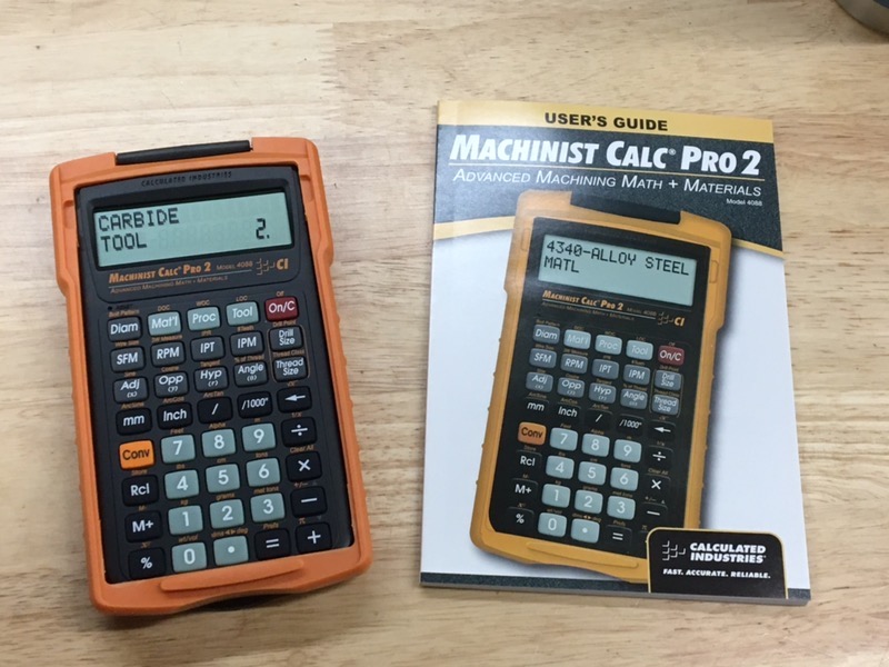
(a little later)
I noticed some things I should report before I forget or get used to them.
0. This is not merely a calculator, it is also a reference book with all the tables you normally would use to make machining calcs manually. As a calculator per se, it can be a little cumbersome. It is also a little clunky to do trig on, which is something machinists do a lot of. I personally have needed trig maybe three times in my life, but I am not a machinist. That said, it does have all the usual trig functions.
This calculator is made for shop floor use. It isn't a scientific calculator and doesn't pretend to be one.
One wag said, "don't make it first year apprentice level" but that's just what it is, and what it should be.
Everything a real machinist learns in their first years, with tables and reams
of paper, stays with them all their working life; this calculator tries to
get rid of the tables and the reams of paper.
If you want something more, get out your scientific one and program it up.
Also, it has an equals key.
[a few gasps are heard from the audience]
Now is when all you RPN fetishists should run screaming into the night, since you won't be able to use this device. :P
 |
| I'll be slightly shocked if this doesn't offend someone |
1. What the hell is a "high performance" tool? The calc offers three tool (cutter) materials: HSS, carbide, and "high performance". At first, I assumed it meant ceramic, since that is the only other cutter material I know of. Since I've never been a professional machinist, I figured I'd stumbled over a gap in my knowledge, and I was about to learn something new.
So I searched the web for "high performance" tools and materials in a machining context, and you know what I found out? Not a damned thing. Everyone says their tool / material / cutter geometry is "high performance". The term is not explained in the manual, as if the reader is expected to know. Maybe it's a regional expression; if you're in Europe or Asia, perhaps everyone uses that term.
In any case, since the only tooling I own (er, I think) is either HSS or carbide, I may just ignore it for now. Later I will probably discover or remember that the inserts I use in my lathe tools, and the inserts for my 3" shell mill, are all ceramic, I dunno. I wonder how I would even tell! ¯\_(ツ)_/¯
2. My experience with calculators that run on coin cells dictates that this MF - which uses one cell not two - is gonna eat batteries like mad. I'll be delighted to be proved wrong if it happens.
(spiffs)
• At any time during any calculation, you can switch between the inch and metric systems without re-entering anything, as should be.
• Fractions are entered (and any number in the display or memory) can be flipped between fractional and decimal display simply by hitting the slash key. Can you remember the decimal equivalent for a 17/64 drill? I sure as hell can't. This changes nothing in memory, so switching what is displayed, or using it to enter a number, will not change how calculations are performed on that number.
• It has more functions than most individual professional machinists
will use, but different professionals will use different function sets.
While reviewing opinions on Home Shop Machinist (which, unfortunately,
is populated by a disproportionate number of grumpy, snarky,
condescending pros and retired pros among the amateurs seeking
knowledge) I found some singing the praises of one feature set (thread
measuring for example - I will never own or use a 3-wire measuring kit
ever, but YMMV) whilst others poo-poo'd that feature and praised
something else.
Your computer can do more things than you will ever use it for too. Relax and enjoy it.
Subscribe to:
Posts (Atom)


